Facebook
 Google
 GitHub
 Linkedin
A Polarizing Discussion: Using Diodes The Right Way Around
Some devices, like switches, are non-polar; you can connect them in either direction. What makes diodes so special, and how can you tell the right way from the wrong way?
In the world of electronics, it’s actually quite surprising how rarely the component device-level world intersects with the field of control and automation engineering. Let’s face it - control engineers don’t want to build circuits. These engineers want to open the box, connect the device to the DIN rail, and screw down the wires. Done. Power it up.
Yet there are times when control engineers must slightly modify a system to include some accessory components. Other times, prototyping a system is necessary, and connecting board-level components is essential to bench-testing the design. For these cases, it’s important to understand how to use those components.
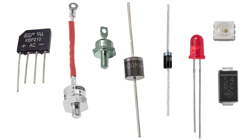
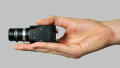
Figure 1. An assortment of various diodes, large to very small (SMD).
Why Are Diodes Different?
One word: polarity. Polarity is a term that means that something has a single direction of orientation. Magnets have north and south poles, molecules have electron density that causes unequal charges, and many electrical devices are created with doped material that only allows electricity to flow in one direction.
Such is the case for diodes, as well as for transistors, which are built from diode P and N material. The category of diodes includes two such examples that might be of importance to control engineers: silicon diodes and LEDs.
Silicon Diodes
Probably the most common use for diode components in automation is to minimize the impacts of inductive feedback, or ‘flyback’ from coil-based load devices that are energized with DC current.
Although this article isn’t meant to discuss the concept of flyback voltage (which is discussed in depth here), in short, the problem occurs when a coil holds a magnetic charge, and then as soon as the device is switched off, the magnetic field collapses and tries to continue forcing voltage into the control device.
To prevent this, we need a device that only allows current to flow in one direction, but not the other. This is a perfect job for a diode.
When the diode is connected to the two terminals of a coil device, say, a solenoid valve, there are two options:
If the diode is connected in forward bias and in parallel with the coil, it will allow all the current to bypass the coil and you’ll end up with a blown fuse.
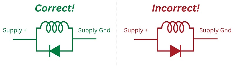
Figure 2. The correct (left) and wrong (right) ways to connect a diode to prevent flyback voltage.
On the other hand, if you connect the diode in reverse around the coil, it won’t allow the coil current to bypass, but if you imagine the coil as a power supply (which it IS, when the magnetic field is collapsing), it will allow the current to travel in a tiny circle from one side of the council to the other, preventing it from reaching any other device.
Locating the Diode Polarity
Silicon diodes are small cylindrical devices (about ¼” in diameter) with wires sticking out each end. Most power diodes have a black body with a gray stripe at one end. Lower-power signal diodes have an orange body with a black stripe at one end. That stripe, whether gray or black, is the cathode end, which points to the end where the current flows OUT.
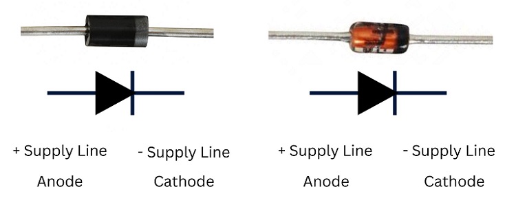
Figure 3. The polarity of silicon diodes in two package styles.
When you connect this in parallel with a coil, be sure to connect the stripe end to the + side of the coil and the non-stripe end to the - side of the coil.
If you mix these up, you’ll find a lot of current bypassing the coil as soon as the circuit is energized. It will probably trip a breaker or break a fuse (I hope you have one installed?)
LED Polarity
If LEDs are used in a prototyping project by themselves, they must be protected with a resistor and they must be connected the right way. For this discussion, I’ll stick to the polarity concept (but please, stick a 2k ohm resistor or something in there, please).
When you look carefully at a normal LED, you’ll notice two symptoms of asymmetry. One sign is that one of the lead wires is longer than the other. The longer wire is the anode, the wire in which electricity ‘enters’ the LED. It must be connected to the + supply source.
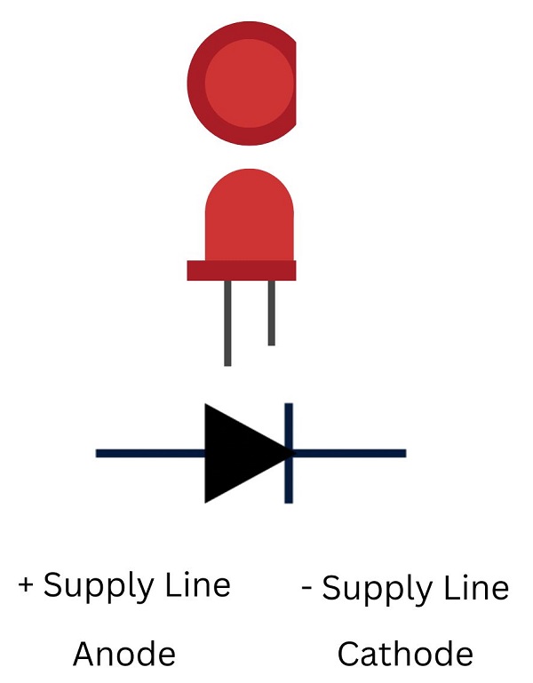
Figure 4. The top, side, and symbol view of an LED showing the anode and cathode.
However, lead wires get trimmed all the time, so it may not be put too much faith in the wire length. The second symptom is that one side of the flange that surrounds the LED is cut with a flattened edge. This flat side is the cathode, and it must be connected to the - supply source.
If you purchase an LED inside a component like a relay or a stack light, the datasheet will clearly define which wire is the + and which is the - input, and they are already protected by a recurrent-limiting resistor.
Transistors
NPN and PNP transistors are built from the same negative (N and positive (P) doped materials as diodes. Therefore, you can’t simply swap out an NPN or a PNP transistor and expect it to behave in the opposite manner; it won’t work at all. If you supply electricity in the wrong direction, no current signal will flow at all.
Most control engineers will not need to install NPN and PNP transistors into a project, unless you are working with microcontrollers (which is a pretty fun hobby, just so you know), so the most critical aspect here is to understand how to read the wiring diagrams for sensor that are built from this NPN/PNP construction.
Control Components - Do We Need Them?
Let’s face it - control and automation engineers just don’t install board-level components all that often. But if you happen to find yourself in a situation where you are prototyping a project or trying to fix a diode flyback situation, hopefully this guide gives you a little bit of valuable insight.
All images used courtesy of the author