Facebook
 Google
 GitHub
 Linkedin
Build A Low-Cost 32-bit PLC | OpenPLC and the ESP32 Microcontroller
Besides using a Raspberry Pi or an Arduino Uno, a low-cost PLC can be built using the popular ESP32 microcontroller. The OpenPLC software supports this popular 32-bit platform.
The OpenPLC platform provides a low entry point into the automation and industrial world by turning small microcontrollers into basic functional PLCs. With such a platform, control professionals can maintain or exceed their PLC knowledge and technical skills in ladder logic programming, hardware architecture, and control systems design.
OpenPLC is not limited to our previously explored Arduino Uno or Raspberry Pi hardware; it can be applied to various other microcontrollers. In this project article, an ESP32 development board manufactured by Espressif Systems will be transformed into a low-cost, functional PLC using a few off-the-shelf components.
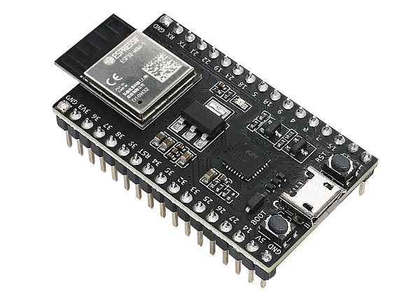
Figure 1. The ESP32 dev kit board. Image used courtesy of Espressif
What is the ESP32 Microcontroller?
The ESP32 is a common approach to various IoT and controller projects with low manufacturing development costs and a highly effective processor. It has become quite popular in the maker and embedded communities because of its low cost, ease of use, and technical support. Some key features of the ESP32 microcontroller include WiFi, Bluetooth, and a small form factor.
- Robust Design
The ESP32 has an operating temperature range of -40°C to +125°C. A supply voltage of +3.3V can power the microcontroller and allow low-voltage wireless remote sensing and controller applications to be developed.
- Ultra-Low Power Consumption
The ESP32 was designed for portable devices, wearable electronics, smart controllers, and IoT applications. The chip has various power modes, dynamic power scaling, and clock-gating features to achieve ultra-low power consumption.
- High Level of Integration
The SoC high-level integration includes the following onboard electronic circuits.
- Built-in antenna switches
- RF balun
- Power amplifier
- Low noise receiver amplifier
- Filters
- Power management modules
- Hybrid Wi-Fi, Bluetooth, and Hardwired Communication Interfaces
Many common communication standards, including Wi-Fi and Bluetooth, as well as SPI, Secure Digital I/O (SDIO), I2C, and UART interfaces, are packaged with the ESP32 to provide other communication schemes between the host and peripheral devices.
With such features, functionality, and versatility, the ESP32 ecosystem can provide minimal PCB footprint requirements to embedded applications. Figure 2 illustrates the functional block diagram of the microcontroller architecture.
A quick observational note: with various subcircuits packaged within the microcontroller, the ESP32 is known as a system-on-chip (SoC) device.
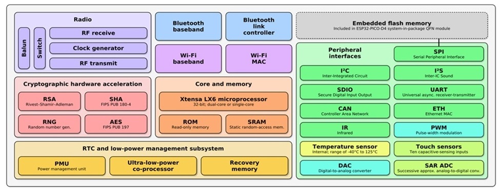
Figure 2. The ESP32 Functional Block Diagram. Image used courtesy of Wikipedia
ESP32 OpenPLC Controller Hardware Setup
The hardware setup is much like the traditional Arduino-OpenPLC controller, consisting of inserting an ESP32 onto a solderless breadboard. Based on the width of the dev kit board, it is difficult to insert the ESP32 into a standard breadboard and be able to connect wires at the same time. If two wires must connect to the same pin, it is impossible.
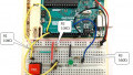
Two options exist: either use two breadboards and connect the ESP32 dev kit over the power rail (as shown below in Figure 3). Alternatively, a saw or multi-tool can be used to slice a standard breadboard down the trench (the low spot in the middle) allowing you to increase the spacing for the ESP32 wiring.
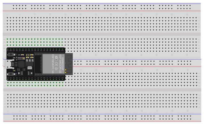
Figure 3. The ESP32 dev kit straddling two breadboards.
With the ESP32 properly inserted, the supporting electronic components can be wired next. As with the Arduino and Raspberry Pi, tactile switches and an LED will be wired to designated general-purpose I/O (GPIO) pins of the dev kit board.
Pins D18 and D19 (GPIO 18 and 19) will provide the input digital control signals for the ESP32.
The input consists of a pushbutton switch with a resistor wired between the switch and ground (a ‘pulldown’ resistor). This parallel connection between the pulldown resistor (10KΩ value) and a switch terminal will provide a control voltage of either +3.3 V or 0 V to the input GPIO pin. The ESP32 also contains built-in pullup and pulldown resistors, so the external resistor can be avoided when the GPIO pin mode is set.
The output LED circuit will be wired to the ESP32’s D2 (GPIO 2) pin. Figure 4 illustrates a pictorial electrical wiring diagram for the ESP32-OpenPLC controller.
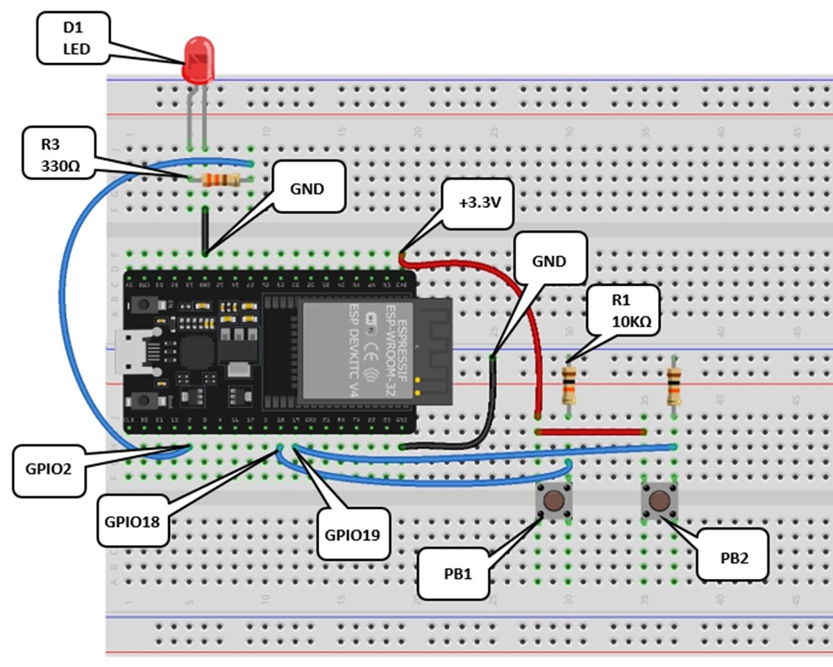
Figure 4. The ESP32-OpenPLC controller wiring diagram.
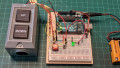
The physical PLC is illustrated next. Note that the LED is the only polarized component. LEDs have one flat edge, indicating the GND connection side.
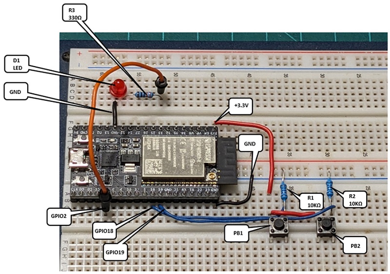
Figure 5. The ESP32-OpenPLC controller hardware.
As an additional reference image, the circuit schematic for the project is illustrated in Figure 6.
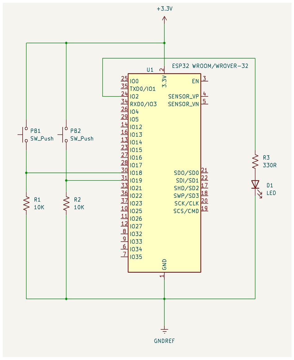
Figure 6. The project schematic diagram.
With the wiring complete, the next step is to build the Start-Stop ladder diagram in OpenPLC.
Building the Start-Stop Control LD
Building the control ladder diagram is relatively easy when using the OpenPLC editor. The basic steps used for the Arduino and Raspberry Pi are applied similarly to the ESP32 controller.
- Define the tag list
- Select the bit instructions (contacts and coils)
- Appropriately wire (connect) the contact and coil bit instructions
- Transfer the LD program to the ESP32
- Test the physical Start-Stop circuit on the controller
Figure 7 below illustrates steps 1-3 with the completed Start-Stop logic.
Notice the internal memory bit instruction named CR. This CR, or ‘control relay’ bit provides an approach to seal, or latch the LED when the Start pushbutton switch is pressed and released.
The CR ‘seal-in’ logic is released by pressing the Stop pushbutton switch, effectively turning off the LED. The digital logic name for this control function is called a Set-Reset (SR) latch.
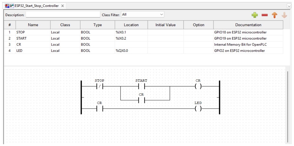
Figure 7. The Start-Stop LD with tag listing.
In this project, you’ll see a column called Documentation, which provides information about the GPIO pins associated with each tag. Such information is helpful during the build phase, matching the electrical components to the ESP32 dev kit board pins.
The LD program is now ready to be transferred to the controller.
Transferring the Program to the ESP32
The steps to accomplish the transfer of the OpenPLC project to the controller are shown in Figure 8.
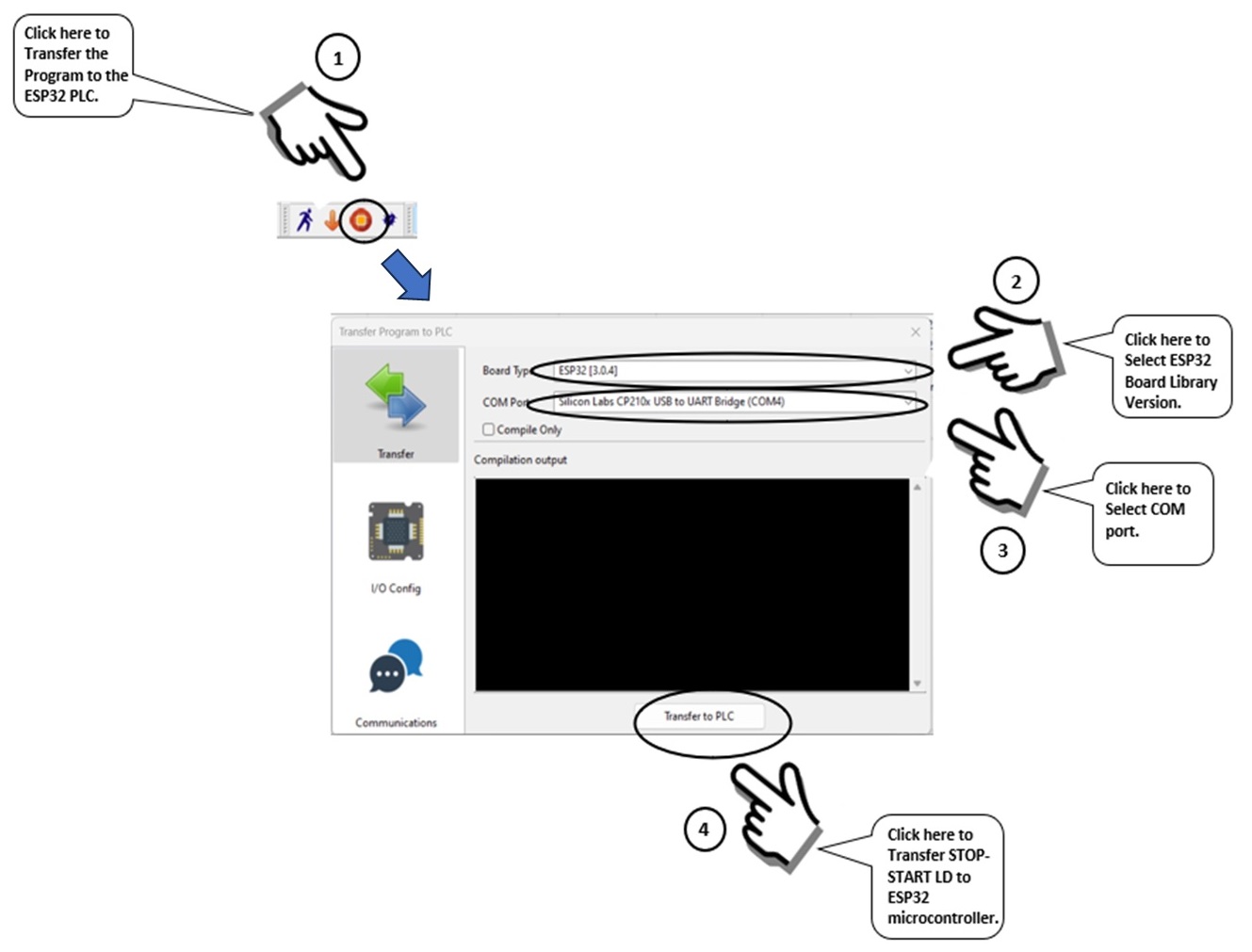
Figure 8. Transferring the Start-Stop LD program to the ESP32 microcontroller.
Transferring the ladder diagram will take several minutes, as software resources must be downloaded from the OpenPLC cloud and installed onto the target PLC development machine. Be patient during this download/installation process.
When the LD program has been successfully transferred to the ESP32, Done! will be displayed in the output window.
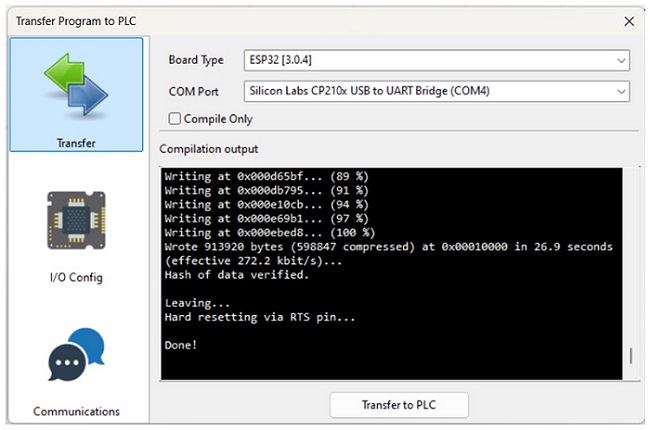
Figure 9. Successful transfer of the Start-Stop LD program to the ESP32 microcontroller.
Pressing the Start button on the breadboard controller will turn ON the LED. Likewise, the Stop button will turn OFF the LED.
This video clip demonstrates the operation of the LD program executing on an ESP32 OpenPLC controller.
To explore the full control capabilities of this controller, add a small DC motor with a driver board. Or program the ESP32 to perform logic functions like the AND, OR, NAND, NOR, NOT, and XOR. Such motor control and logic functions illustrate the industrial control applications of OpenPLC on a desktop.