Facebook
 Google
 GitHub
 Linkedin
CIP Safety and Its Applications to Robotic Installations
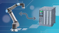
Industrial robots are becoming safer and more economical by utilizing safety signals over Ethernet networks via CIP safety technology.
What is CIP Safety?
Common industrial protocol (CIP) safety is a technology used to transmit and receive safety signals over an industrial network. Instead of hard wiring light curtains and door switches, a simple Ethernet cable can be plugged into these devices and their signals will be available to safety PLCs or some advanced safety relays. Typically, CIP safety devices will communicate with a safety PLC, such as the GuardLogix family of PLCs from Allen Bradley. These signals can be customized to transmit the required signals, along with some diagnostic signals.
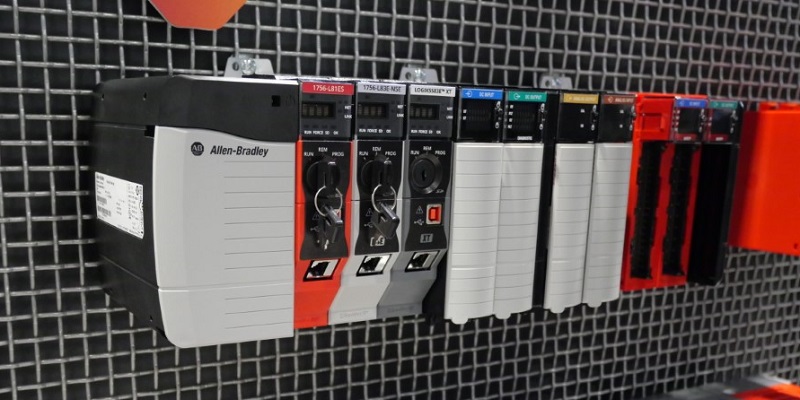
Figure 1. Safety PLCs and I/O modules.
Combining CIP Safety And Robots
CIP safety has been around for many years now and it is typically found in use with input and output modules found in panels or in the field. Servo drives like the Allen Bradley Kinetix family of servo drives have made use of CIP safety for well over ten years.
Many robot manufacturers are now offering an option for CIP safety on their industrial robot packages. This option will supersede hard-wired signals, saving valuable time during the initial commissioning phase. The safety system runs on a separate CPU so any heavy computing loads within the robot controller will not affect the speed of the safety system. The safety CPU typically runs faster than the robot CPU so applications with shared robot space or restricted space can be handled within the robot safety and the safety PLC.
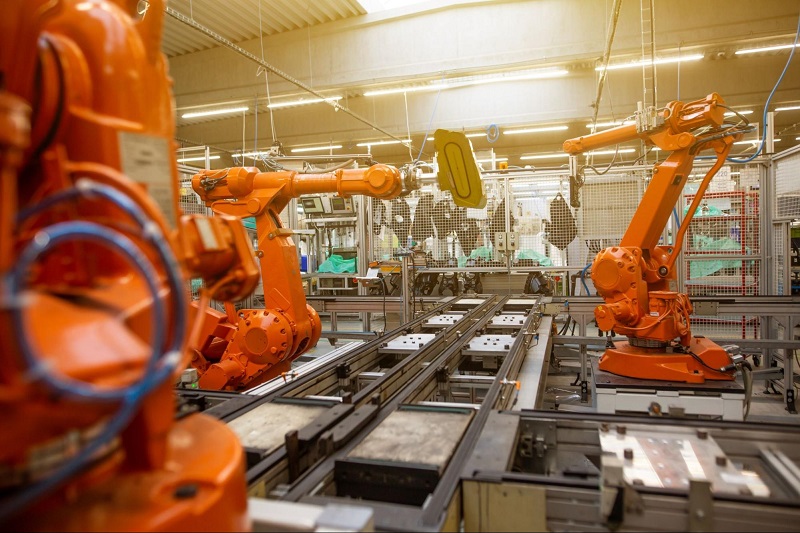
Figure 2. Robotics in an automated factory. Image used courtesy of Unsplash
Robot Safety
Perhaps this goes without saying, but any automated equipment that utilizes industrial robots will require some kind of safety system. The complexity of the safety system will be directly related to the complexity of the equipment. Some robotic systems only require one dual-channel safety signal. If an E-stop is pressed or a door is opened, the signal will go low, and then once the safety system is satisfied, the signals will go high again. This level of safety can support a simple safety relay, but if your system is more complex and requires multiple safety input devices, you might run out of discrete I/O and will need to purchase additional I/O boards, if they are even available.
Today, most larger industrial robots come equipped with (or have the option for) an external safety system that monitors the robot arm and TCP to ensure the robot stays inside a designated zone and safely removed from other zones. Speed limiting and TCP orientation monitoring is typically also offered with these options. These features can also have I/O that will output the status of the feature to satisfy ‘enable’ inputs of controllers. These signals would typically have to be wired back to safety inputs or outputs, and with safety I/O often costing more than double what non-safety I/O costs, these features can become quite expensive.
With CIP safety, signals can be added without additional wiring or costly I/O cards. If, during integration, you decide to add a prohibited zone and enable it with an input, there would be no additional hardware required.
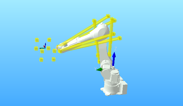
Figure 3. Tool arm monitoring zones.
Using CIP Safety With Robots
Configuring a CIP safety robot is actually pretty similar to configuring a standard robot. You will need to add a generic Ethernet module to your Ethernet map in your PLC code, and you will also need to add a generic safety module. The safety module connects to the CIP safety controller in your robot. Sometimes this requires a separate Ethernet cable, but most times, a single cable will work for both safety and non-safety communications.
Once the module is added, you will need to configure the data input and output size along with any configuration size. Probably best to refer to your specific robot manual for these settings. Some robots will require a safety configuration number that would be generated in the robot when a configuration is changed. If these configuration numbers do not match, your modules will fault and you will lose communications. If your robot doesn’t support this feature, simply turn off the configuration number check.
Once the generic Ethernet modules are configured and communicating, you can now focus on the robot configuration. In most robots, you will need to create an allowable zone, defined around your TCP and/or robot arm. The zone around the TCP should encapsulate your entire gripper. The allowable zone should reflect the location of the guarding or fence around the robot. If you have shared areas or restricted areas, you can create prohibited zones that can be enabled with signals from your PLC.
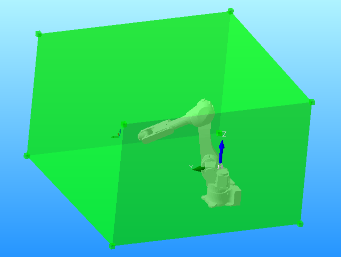
Figure 4. Constant monitoring zone: allowable zone
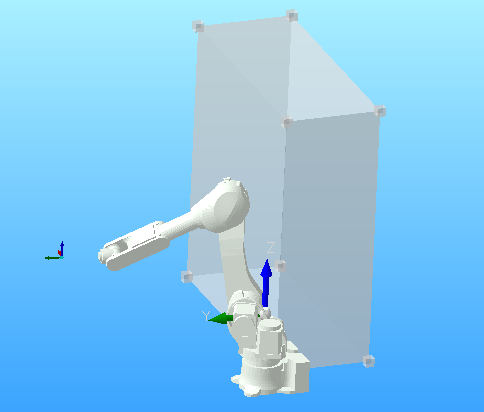
Figure 5. Select restricted zone
Enable Restricted Zones
This is where the value of CIP safety communication really pays off. A typical application might include two robots that need to interact or work in the same area, for example, a dial nest with one robot placing parts in the nest and one robot picking parts from the nest. There are several ways to monitor the robot's position without CIP safety, but you will need to depend on the speed of the PLC and the I/O to stop the robot in time.
If we create a zone in robot 1 and robot 2 where the dial nest is, and we output a signal when either robot enters this zone in the PLC, we can send that signal to the other robot’s safety system to enable the restricted zone. If robot 1 were to get the command to enter the restricted space while robot 2 is occupying the restricted space, the safety system in robot 1 will stop the robot once it breaks the zone wall, preventing costly collision and downtime.
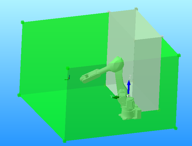
Figure 6. Both allowable and restricted zones
Other Applications of CIP Safety
The example above is only one simple scenario where using CIP safety and an advanced robot safety system can not only save time and money during the design phase but can also help prevent costly crashes that can not only damage equipment but also result in downtime of production equipment.
Designing and configuring these systems has become much easier over the years, and there is a lot more flexibility in the features which allows designers to create even more complex robot applications. Consider purchasing a safety system option for your next robot application and you are likely to start seeing the benefit from the very first day.