 Facebook
 Google
 GitHub
 Linkedin
Comparing Single-Phase vs Three-Phase Motors
In this article, learn the differences between single- and three-phase motors, including how each one works and applications best suited for each type.
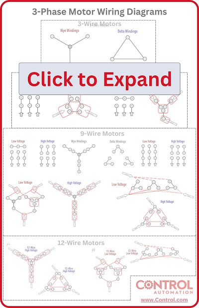
Check out Control Automation's exclusive eBook on motor wiring

There are three main categories of motors:
- DC
- Single-phase AC (1-Ph AC)
- Three-phase AC (3-Ph AC)
Even within those main categories, there are many variations and strategies. DC motors have some unique properties, but usually, the operating principles between different AC motor variations can become unclear. Understanding those differences can explain the reasons why some situations can only use one type of motor and not others.
Motors operate using the principle of magnetic fields generated by coils of wire. In the unique situation of a DC motor, the poles of the magnetic field must be somehow switched externally. This is most often accomplished with commutator brushes, or perhaps by alternating the voltage with an external driver circuit (such as in a brushless or stepper motor).
When it comes to the naturally alternating voltage curve of AC, this creates an ideal situation for driving the motor without the bulk of the extra circuitry or noisy, inefficient carbon brushes. Alternating voltages are the perfect supply for moving heavy loads with as little loss as possible. However, even between the two voltage systems (1-Ph and 3-Ph), there are differences in operation leading to advantages and disadvantages depending on what the application demands.
Are you a motor troubleshooting expert? Quiz yourself with our (no pressure) worksheet!
Single Phase Motor Operation
Inside a single-phase motor, the main drive coil is actually a series of coils distributed equally around the inside to smoothly drive the rotor inside. The voltage will be applied, leading to each coil alternating north and south at the main line frequency. The rotor will be magnetized to those poles, carrying it in a continuous circle.
This works while the motor is running at full speed, but there is a problem at start-up. The rotor will come to a halt at a random place when the motor is turned off, so the next time the voltage is applied at startup, it’s hard to know whether an N-S magnetic attraction will cause it to go forward or backward to begin its rotation at startup. A random rotation direction is obviously unacceptable.
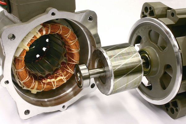
Figure 1. Cutaway of a single-phase motor.
The most common method of correcting this problem is by using a capacitor in series with a secondary coil, usually called a ‘starting coil’. Since the nature of a capacitor is to apply a burst of current at the very beginning of a voltage waveform, the current through this starting coil will occur a fraction of a second before the main coil. This causes the rotor to be attracted first to this start coil, then to the main drive coil in close succession, providing a predictable rotation direction.
The polarity of this start coil can be reversed to reverse the startup direction. Once the motor is sufficiently started, a very distinct “click” will indicate that a centrifugal switch has opened up the start coil, its job being finished. A bulge on the side of the housing usually contains the capacitor, so if that bulge is present, it is almost certainly a capacitor-start, single-phase motor.
These single-phase motors have advantages when the voltage supply is a house or a shop without a three-phase supply. The wires into the motor will consist of just the Line and Neutral from a standard 120-volt supply, or the two Line wires in the case of a 240-volt system. In either case, this single circuit of conduction must contain the entire driving current.
If the horsepower demands of the motor are large, the wires must be huge. This leads to the main disadvantage of single-phase motors: they will usually only be used for smaller applications. But regardless, since single-phase supplies are so common, this type of motor is found everywhere on shop machinery.
3 Phase Motor Operation
Many of the driving principles of the coils inside of a three-phase motor are exactly the same as the single phase. The only difference is that with three phases, the magnetic poles of the coil progress in increments of ⅓ of the way around the rotor as each Line reaches full voltage. This means that depending on the sequence of coils being magnetized, the direction of rotation will no longer be random as it was in the single-phase motor - it’s completely predictable and consistent. The starting circuit with the capacitor is no longer necessary since the motor drives quite naturally.
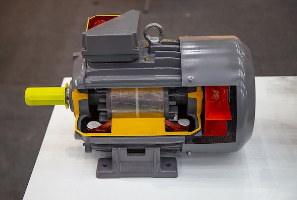
Figure 2. Cutaway of a three-phase motor
The main advantage of this kind of motor is in large-power applications. The supply and conductors are normally capable of providing larger amounts of current than residential systems in the first place, and each of the three Lines will carry less current individually than if the entire current was traveling through one circuit. This makes the motor appealing in larger power applications. In the case of most three-phase motors, the wiring can be configured for either high or low voltage by the electrician. This can decrease the current consumption if a higher voltage supply is provided.
An obvious disadvantage of this kind of motor is that a three-phase supply must be present to drive such a motor. With modern control systems, this is actually not always the case, since some low-power Variable Frequency Drives (VFDs) can be supplied with single-phase power, but deliver three-phase current.
Three-phase vs Single-phase Motor Applications
For most small shop applications that require motors with low power consumption, it would be normal to see a single-phase motor with a capacitor starting coil. For reference in terms of ‘power’, a five horsepower motor run at 240 vAC would consume about 15 amps.
Run at only 120 vAC, this same 5 HP motor would consume 30 amps. This is quite a significant amount of current. For larger industrial applications, the natural solution would be a three-phase motor since the voltage and current supplies are much larger. There is an ideal solution for nearly every motor application!
Interested in more content about motors? We have plenty to choose from!
Articles:
- 3-phase Motor Types: Synchronous and Induction Motors
- Understanding Delta Wound Motors for Industrial Applications
- Common Motor Windings and Wiring for Three-Phase Motors
- Brushed vs. Brushless DC Motors
- Field-oriented Control (Vector Control) for Brushless DC Motors
Textbook:


Excellent explanation