Facebook
 Google
 GitHub
 Linkedin
Comparing Voltage: When to Ground a Floating Power Supply
The choice to ground or float a power supply is not always clear in the NEC. This article explains floating or fixing a DC supply with respect to ground and how circuits can be functionally constructed both ways.
There is quite a bit of discussion, and perhaps even some folklore, around whether to use “grounded” or ”floating” power supplies in instrumentation, data acquisition, and control systems. The choice to ground or float a power supply is sometimes clearly stated in the National Electric Code (NEC), but in other cases, it is not and is left to the discretion of system engineers.
The purpose of this technical article is not to give an answer for every potential grounding situation but to point out some of the considerations that must go into the decision. It is more about learning what questions to ask rather than providing direct answers.
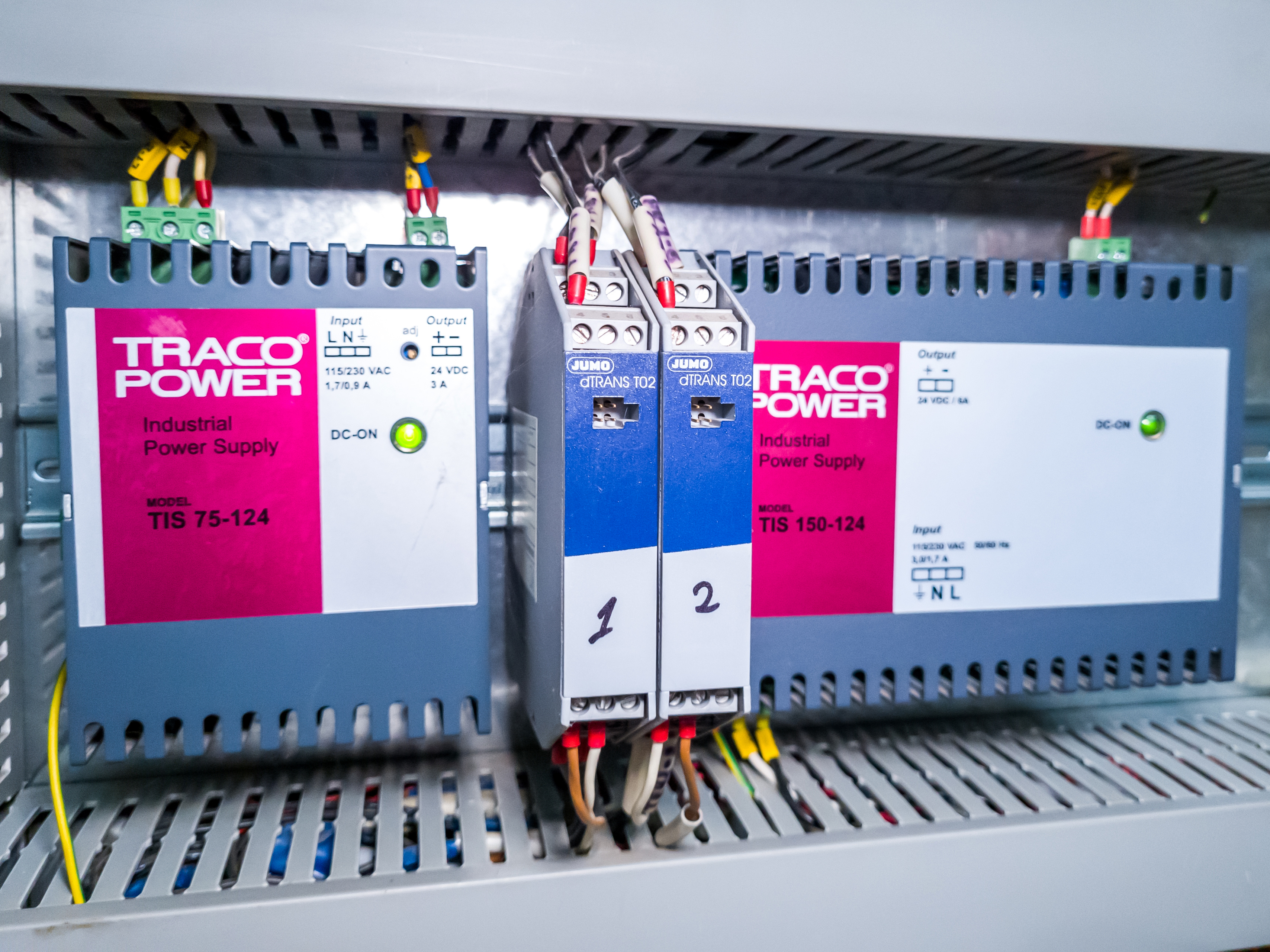
Figure 1. The choice to ground or float a power supply is not always clear in the NEC. Image used courtesy of Adobe Stock
NEC Grounding Regulations
Before deciding on a grounded or floating system, system engineers should consult the NEC, as it dictates the legal standards for what and how different devices should be grounded or left ungrounded. Systems that do not follow the NEC are major safety violations, which may result in workplace fatality, injury, equipment damage, or fines.
The NEC is updated every three years, and the newest version will be released this year (2023).
Advantages of Keeping a Power Supply Grounded
While this article is not meant to be a full primer on grounding or the philosophical question “what is ground?”, it is important to understand why systems are grounded. Mostly, this article will speak of chassis grounds, where the metal covers of devices are electrically connected. These connections can be through wires, braided straps, copper strips or bars, DIN rail, or other such connections. Vehicles employ chassis grounds to ensure a safe path back to the negative battery terminal, while still not conducting any current to the physical ground outside.
Grounded systems are ones where all components are tied together and have a common node. The assumption with grounded systems is that there is no voltage drop across the bonding wires or chassis and that all pieces in this system can use this shared ground as a reference point for voltage measurements.
To take the ground concept one step further, specifying ‘earth ground,’ or simply ‘earthing’ in many geographies, implies that the ground is connected to a physical grounding rod outside the facility.
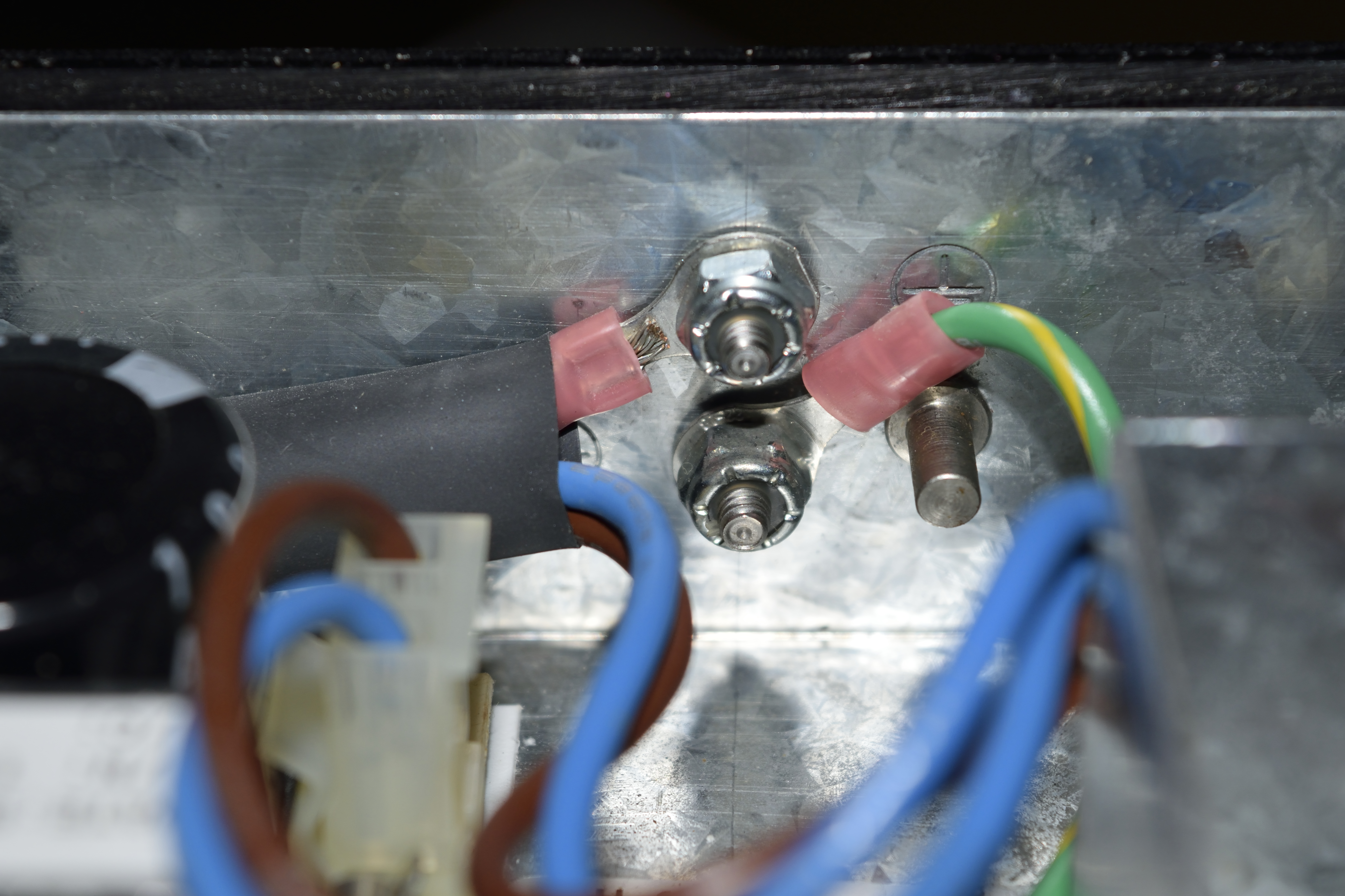
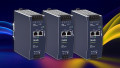
Figure 2. Chassis ground. Notice there are multiple electrical connections to the steel box of this device. Image used courtesy of Wikimedia Commons
Grounding for Safety in the Workplace
Grounds are often tied to the chassis of a device. This way, if there is an internal short to the chassis, the current can flow directly to ground. Typically, this trips a breaker or blows a fuse, stopping the current flow altogether.
The most common reason for tying grounds together is to prevent dangerous electrical shocks. In general, if two pieces of equipment are within arm’s reach of each other, their grounds should be tied together. If they are not tied together, the two machines may have a voltage difference. If a worker touches each machine, and the potential difference is high enough, the worker could receive a dangerous electrical shock.
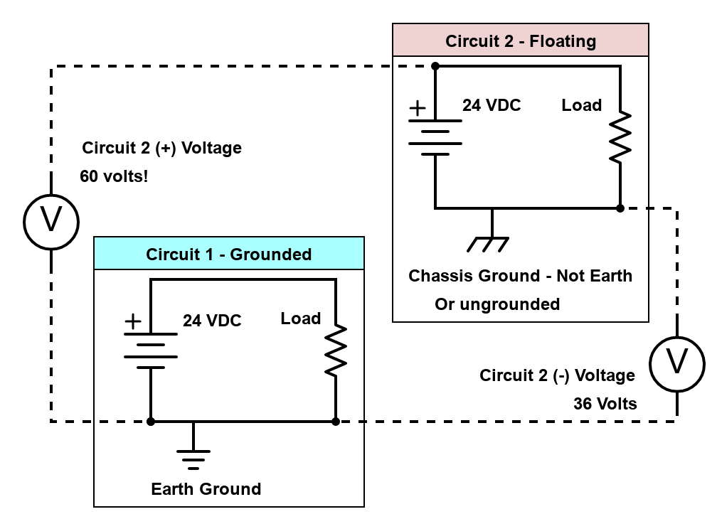
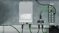
Figure 3. One 24 V device tied to earth ground (left) next to a 24 V “floating” power supply (right) set to an arbitrary 36 V level.
Consider two 24 V DC devices within arm’s reach of each other. One 24 V device is tied to earth ground, meaning the high voltage (with respect to ground) is 24 V. The other machine chassis has lost its earth ground. Instead, some other power system (or induced voltage) has raised the potential of the entire system to 36 V. There is still only 24 V across the components in this second system, but there is now 60 V from the top of the power supply to ground. This is an example of a “floating” power supply.
If someone were to touch the chassis of the first and second devices, even though they both SHOULD be zero volts with respect to ground, the second system is floating 36 V higher. The operator receives a shock.
Advantages of Ungrounded Power Supply Systems
Two advantages of floating systems are their ability to isolate equipment and the potential to lower noise on sensor signal lines.
The Trouble with Finding Common Ground
While there are advantages to tying one end of all equipment to ground, sometimes that is not practical.
Consider a large installation of health monitoring sensors on a bridge. They monitor small resistance changes from strain gauges to ensure that the bridge behaves predictably under normal use and wind loading. Often, these strain gauges are fed through a Wheatstone bridge to measure a small voltage change when the bridge is strained. Because this voltage is small, and yet the distance the signals might have to travel is large, a common ground may not be so “common,” meaning that the voltage at any point along these sensor ground wires might not be zero. Such ground loops can wreak havoc on carefully calibrated sensors. In this instance, it might be better to ensure that each sensor is isolated from a common ground, measuring only the voltage change (and thus the resistance and therefore, the strain) across the gauge itself.
Along these lines, a long wire can act as an antenna, even if one end appears grounded. Because of this, all manner of radio frequency interference (RFI) can be absorbed by this long antenna wire, causing even more differences in “ground.” These can be particularly problematic to troubleshoot as they change with time and can be intermittent, depending on the source of the RFI.
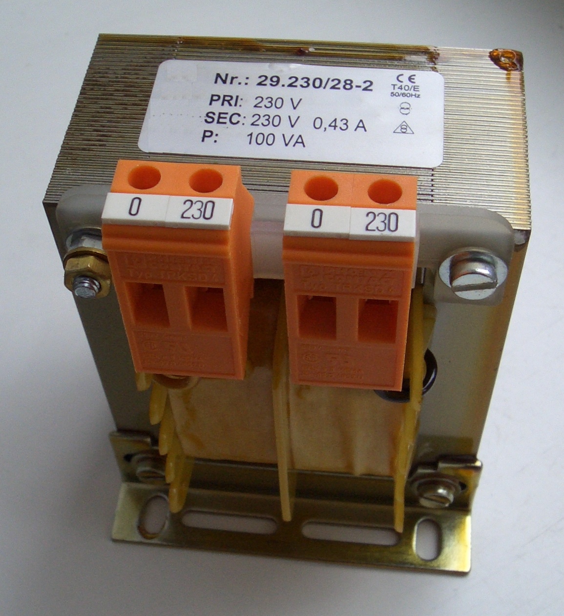
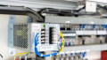
Figure 4. Isolation transformers are good at filtering out high-frequency signals. Image used courtesy of Wikimedia Commons
Electrical Isolation
Isolation also has its advantages for limiting high voltage spikes and impulse signals. Back to the bridge example—consider that there is a set of sensors and data acquisition hardware, all tied together through a common ground. Then, as happens frequently, the bridge is struck by lightning. While many such structures have some lightning protection, it is not perfect. Suddenly, the “ground” is instantly spiked to 100,000 V. Everything on this system will be reverse biased to the tune of 100,000 V minus whatever voltage is on the positive side. The chances are high that devices connected to this ground will be destroyed.
The lightning example makes a good case for isolation in large outdoor installations of sensor hardware. Suppose instead of connecting all of these devices through a common ground, the data acquisition system and power supply are left floating, connected through an isolation transformer. In that case, the voltage spike will be less likely to damage the more expensive hardware. Transformers (and inductors, for that matter) are good at filtering out high-frequency signals, including impulses, meaning that the voltage spike will be attenuated before traveling back into the protected hardware.
It should be noted that isolation transformers and floating grounds are NOT adequate lightning protection. They can be used as part of a more comprehensive lightning protection system.
To Float or Not to Float?
Within the extent of the law provided by the NEC, the engineer has some flexibility on how each system can be designed or modified to meet their particular needs. Large systems with long wires often benefit from floating connections, as ground loops may be unavoidable, and voltage spikes are more common. More compact systems, particularly those that could be easily or accidentally connected, should share a common ground.