Facebook
 Google
 GitHub
 Linkedin
Design a GRAFCET-Controlled Pneumatic System in FluidSIM
Learn how to use Festo's FluidSIM software to design and simulate a pneumatic cylinder extension system using GRAFCET as the control method.
In pneumatic systems, simulation helps identify issues in early design stages while also showing how the system is expected to run. Tools like Festo’s FluidSIM can handle the design, simulation, and provision of an integrated control system known as a GRAFCET.
What is a GRAFCET Diagram?
GRAFCET, or “Graphe Fonctionnel de Commande Etape Transition,” uses a structured and graphical method to implement control logic for pneumatic or automation systems. This control method provides simulation options so the control system can be tested before deployment into the physical system.
By breaking complex systems into manageable steps and transitions, the design process can be done in a more organized format. This tutorial aims to show the steps of how to create a simple GRAFCET-controlled electro-pneumatic circuit using Festo's FluidSIM environment.
For our tutorial example, we will implement control logic such that when the pushbutton is pressed, the cylinder extends and then waits 4 seconds before retracting.
Creating a New Electro-Pneumatic Circuit and Adding Labels
To get started, open the FluidSIM software and create a new project. You can explore our introductory article to get started with FluidSIM.
We will begin by adding a double-acting cylinder, a 5/2 solenoid valve, and a compressor supply, then connect everything as shown below.
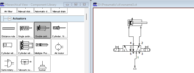
Figure 1. Double-acting cylinder, solenoid directional control valve, and compressor's pneumatic circuit.
Labels will be assigned to the two valve solenoids: YV1 and YV2. The magnetic proximity switches will be labeled SQ1 and SQ2. These labels are essential for the identification of the components in relation to the electrical connections. To add labels, right-click on the component, then select properties, and a text input box appears.
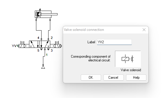
Figure 2. Add the solenoid valve connection label by right-clicking on the grey circle on the DCV and adding the label property.
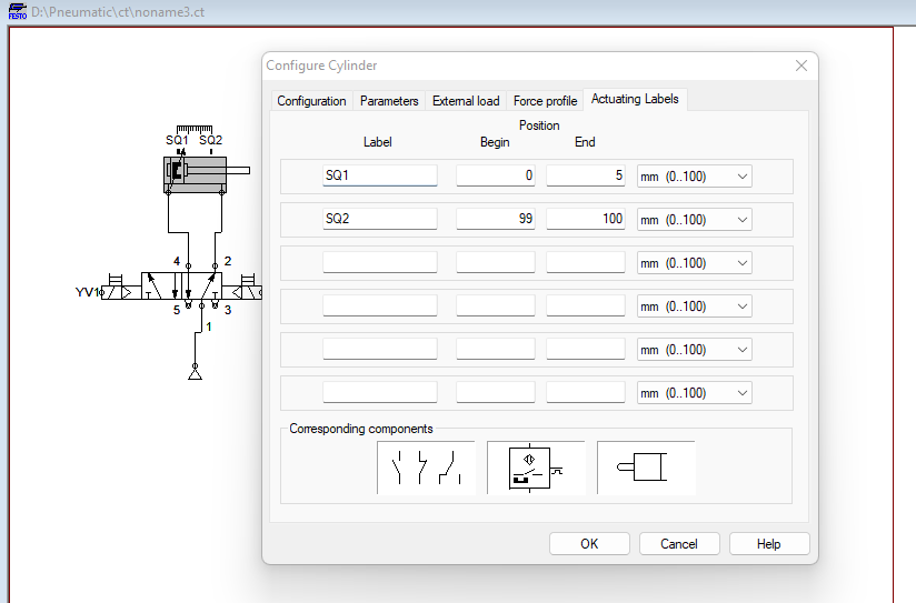
Figure 3. Add actuating labels to the cylinder with a maximum stroke of 100 mm. The SQ1 switch is positioned between 0-5 mm, whereas SQ2 is positioned between 99-100 mm relative to the cylinder's stroke.
GRAFCET I/O and Electrical Connection
With the pneumatic circuit ready, add the GRAFCET I/O module by dragging it from the GRAFCET components library and placing it on the design window. Other components to be added to the circuit are magnetic proximity switches, power supply, and solenoid valve relays.
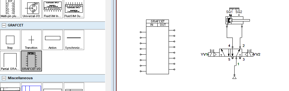
Figure 4. GRAFCET I/O was added to the design window for connection.
Once all the electrical components are added to the design window, connections can be made for the two solenoid valves, the proximity switches, and a pushbutton as shown in the figure below.
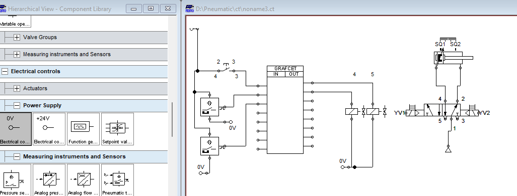
Figure 5. GRAFCET I/O connection with proximity sensors, pushbutton inputs, and solenoid valve outputs.
Assign labels to the proximity switches and the solenoids, identical to the ones in the pneumatic circuit. This is done in a similar fashion as with the pneumatic circuit labels before.
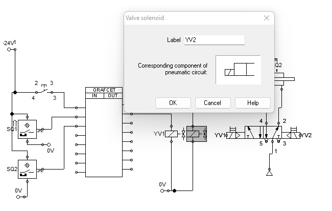
Figure 6. Add the label property of the two solenoid valves in the electrical circuit as YV1 and YV2.
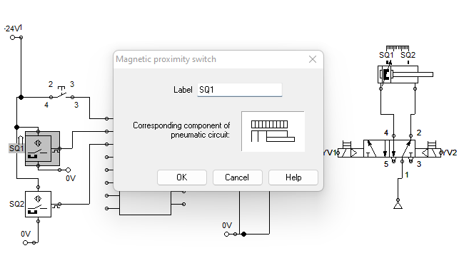
Figure 7. Add the label property of the two proximity switches in the electrical circuit as SQ1 and SQ2.
When it comes to adding labels to the GRAFCET I/O, you can define the labels for the connection that will later be used as a variable to create the sequential logic. To add these labels, right-click and add the property labels as shown below.
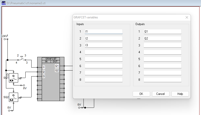
Figure 8. Adding the property labels the inputs and outputs connected to GRAFCET I/O.
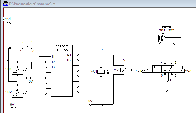
Figure 9. Final circuit after addition of labels and GRAFCET I/O variables.
Modeling the Control Logic using GRAFCET Components
GRAFCET involves a sequence of steps that only execute when transitional conditions are met. Remember our example: we are going to use the pushbutton connected to I1 to extend the cylinder, then wait for 4 seconds before retracting.
To initialize the sequence, we need to add a step to the design window. Add a step, then click on properties and set the step to ‘Initial’ to wait for a start signal. For this example, we are going to use consecutive numbers starting with ‘1’ as the step names.
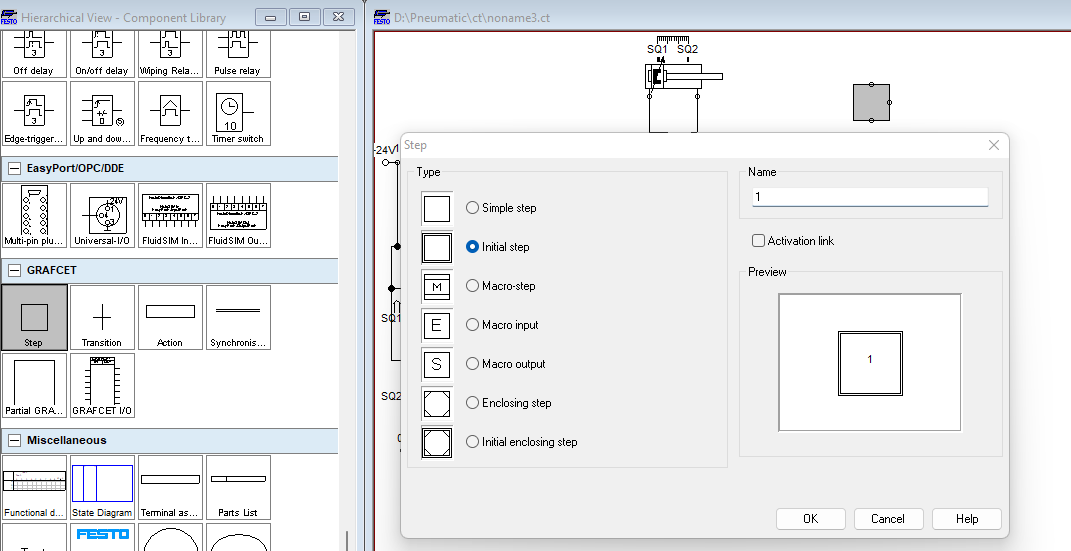
Figure 10. Setting up and naming the initial step.
Add a transition just below the initial step where the conditions of the I/O variables are defined.
The first condition will be the state of I1, which is connected to the pushbutton to start the whole system. To do this, click on variables and add I1 as the variable for the transition. Add the statement ‘START’ in the name text box.
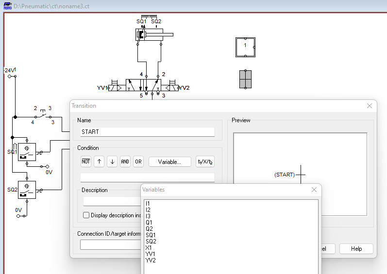
Figure 11. Transition variable and name settings.
We now add a second ‘Simple’ step and add an ‘Action’ component, as illustrated in the following two figures.
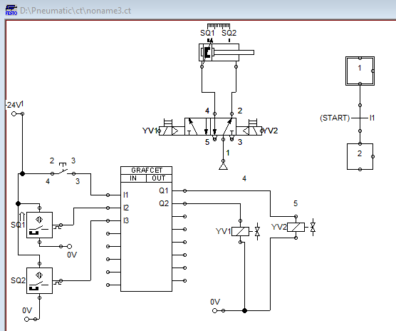
Figure 12. Adding the second step, a ‘Simple’ type.
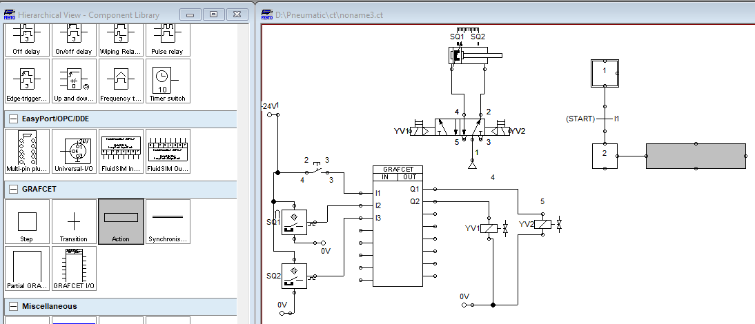
Figure 13. Adding the Action component connected to step 2.
The action is tied to Q2, the extension solenoid output, and the logical description of ‘Extend Cyliner’ is given.
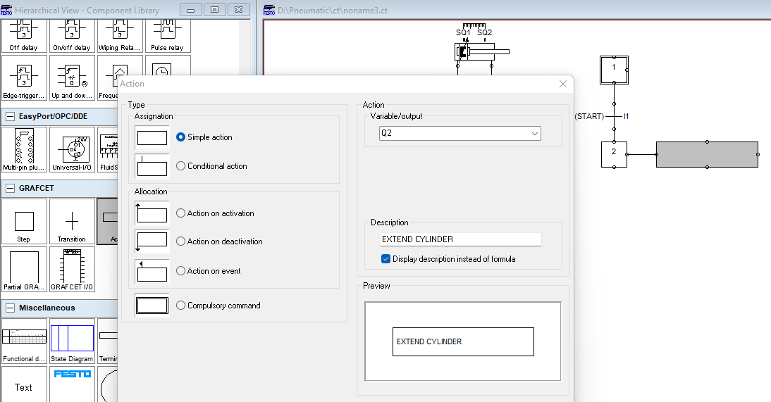
Figure 14. Adding the output variable for the action.
With the cylinder extension action complete, we can now add a transition and a delay property for transitioning to step 3. This delay allows the cylinder to wait for 4 seconds before the cylinder retraction action in step 3.
The transition name can be set as DELAY and by clicking on the last condition in the condition variable selections, we can define the time delay and the input variable for SQ2. Alternatively, we can add the syntax (4s/I3), where 4s represents a 4-second on-delay timer that begins when input variable I3 is energized, after which the transition is triggered.
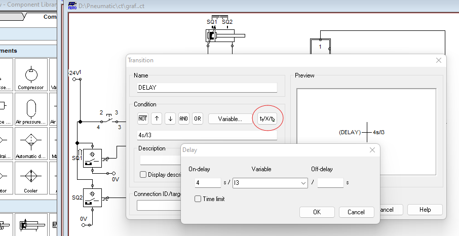
Figure 15. On-delay transition for step 2.
Repeat the action for Step 3, except this time, we need to attach the variable Q1 and choose ‘Cylinder Retract’ as the description.
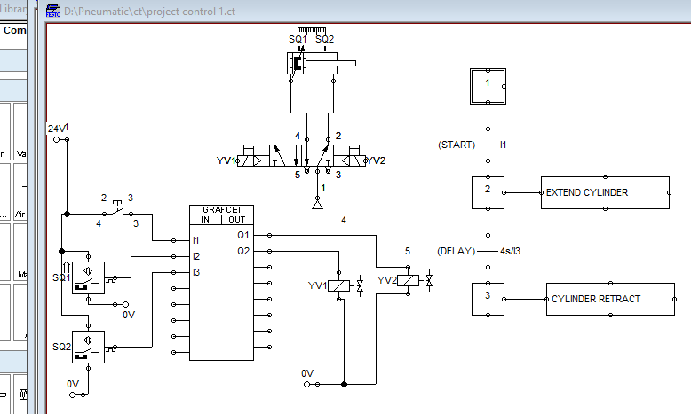
Figure 16. Add an action to retract the cylinder.
Finally, once the cylinder is fully retracted, the retract switch input, I2, will return back to the initial step completing the loop with the transition named LLS (lower limit switch).
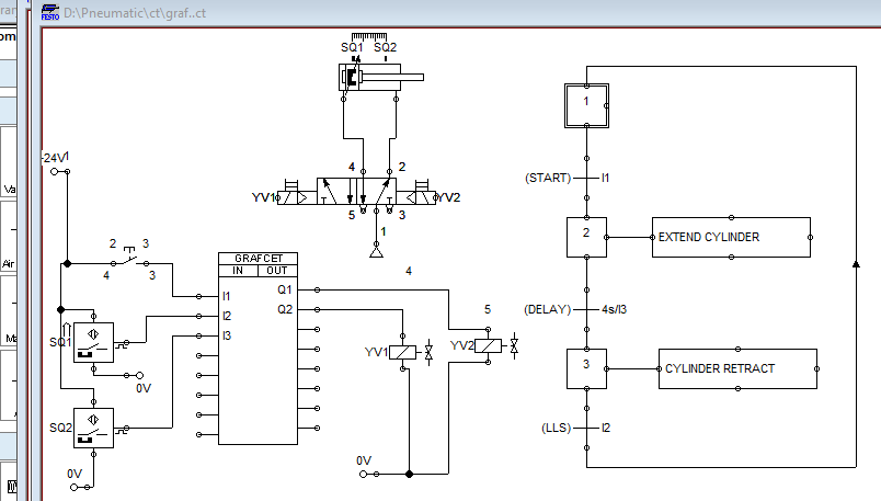
Figure 17. Final transition with a loop back to the initial step.
Simulation Results of The GRAFCET Controlled System
When the push button connected to I1 is pressed, the cylinder extends, then delays in the extended position for 4 seconds. At this time, the second step is highlighted with a green border. Once the four seconds have elapsed, the cylinder retracts, as illustrated by the sequence of simulation images below.
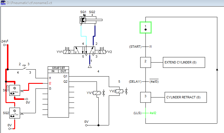
Figure 18. Simulation: before clicking the start button.
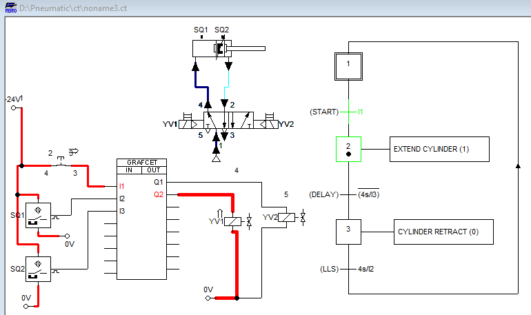
Figure 19. Simulation: after the start button is pressed.
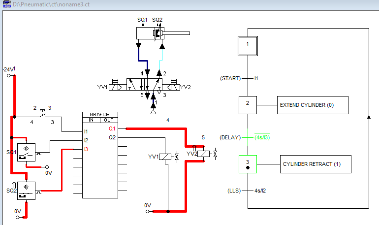
Figure 20. Simulation: delay before retracting the cylinder.
Why Use GRAFCET for Pneumatic Control?
The use of GRAFCET to design a pneumatic control system can prove useful before project deployment as it offers a simple sequential and graphical approach to designing a control system. This makes it a potential option for anyone working in the automation sector who has some understanding of how to use tools like FluidSIM for design and simulation.
With more exploration of the practical design of pneumatic systems, you can quickly grasp the concepts relayed in the tutorial and become an expert in electro-pneumatic circuit design and simulations.
All images used courtesy of the author