Facebook
 Google
 GitHub
 Linkedin
Electrical Instruments and Gauges: Connection and Configuration
In any process industry, transducers are the basic instrumentation unit for continuous monitoring of system variables that provide inputs for control system algorithms and outputs.
Electrical instrumentation includes the devices and systems used for measuring the momentary value of important automation process quantities. Electrical quantities like current voltage, resistance, frequency, and active and reactive power are the most critical parameters of any power generation, transmission, and distribution system. In other process systems, these might also include non-electrical properties like temperature, position, pressure, and flow rate.
What are Electrical Instruments and Guages?
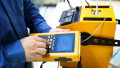
Within the central control rooms of modern power plants, we can supervise, control, and monitor the electrical parameters using SCADA and DCS systems. Generally, these control rooms no longer use panel-mounted instruments and mechanical gauges to display voltage, frequency, current, etc. However, the digital panel meters are usually installed on the front door of the enclosure of the unit's local control panel (ULC), governor panel, and excitation control panel.
In the past, for instance, let us consider a situation where an operator hears the generator hum loudly. He would look at the indication lamps on the switchboard to see which breaker has tripped open. If any are tripped, the other helpful instruments and gauges will show points of information that would be otherwise impossible for anyone to discern accurately by seeing and hearing.
From the above example, it is clear that instrumentation is a prerequisite for safe and reliable operations for monitoring, controlling, and recording any disturbance in the generation, transmission, and distribution system. Specific instruments like sensors and transmitters are mounted on the process area to report the indications or measurements to the central control room system.
The following types of information, including indications/alarms and analog values related to hydro-generating units, are being displayed in the operator workplace:
- Unit’s MW, MVAR, and energy
- Generator terminal voltage and currents
- Turbine speed in rpm, cooling water pressures, brake system pressure
- Wicket gate position, stator winding temperature, transformer oil/winding temperatures.
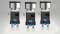
Transducers are a part of the large data acquisition system installed in corrosive environments, usually near the process, and their purpose is to convert physical quantity (pressure, temperature, etc.) or electrical quantity (current, voltage, frequency, resistance) into desired output electrical signal (voltage, mA, or protocol) for any control system for accurate measurement.
Example with a CEWE Programmable Transducer
The CEWE programmable transducer model is DPT521-401. This transducer connects to 3-phase line voltage (U1-U3 and N) and 3-phase current (I1-I3). It has four analog outputs that can be configured for any measurand quantities by selecting predefined dropdown list options, like active/reactive power, current, voltage, frequency, and often more.
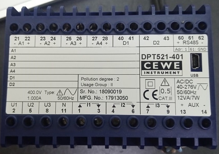
Figure 1. Our example transducer, the CEWE Instruments DPT521.
The following hardware and software accessories are prerequisites for programming the transducer:
- A standard USB cable connects to a laptop for parameter settings
- Proprietary software called “ConfigView” to configure the input and output for the 220 kV transmission line for MW and MVAR values
- Setting the CT/PT ratio for the transmission line. 230 kV to 110.7 V and 1200A to 1A
- Configure the analog output of the transducer to transmit the signal (maximum 0-10 v or 0/4-20 mA) for RTUs or PLCs to calculate engineering values for the operator’s display
- Set digital outputs (DO) for energy import and export of line
- Back up the settings file
Setting up the Connection and Power Supply
To set up the physical connection, we need the following arrangements:
- Programmable transducer, in our case, CEWE Instruments model DPT521-401
- AC or DC (40-276 V) auxiliary power supply input for the transducer
- An RS-485 multi-drop connection or standard USB port is available for connection. The supported communication protocol is Modbus RTU.
- The laptop is pre-installed with ConfigView software
Connecting to the Transducer Using Software
The first step is to add the product. We select transducer from the options. For this, open the “ConfigView” software icon and click on “File->Add transducer” as shown in Figures 2 and 3 below:
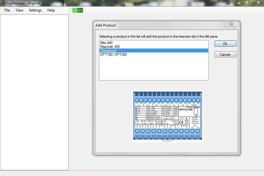
Figure 2. Add the product for the treeview list in the left pane.
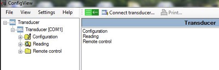
Figure 3. The treeview list in the left pane for configuration
Next, click on the “File->Connect transducer” as in Figure 4. A new popup window appears which shows the connection properties like com port (your COM# might be different), USB connection (virtual RS-232), and baud rate (if using a serial connection).
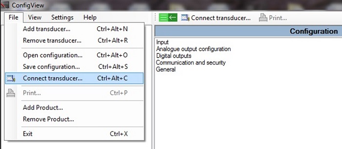
Figure 4. ConfigView software to connect the DPT over USB
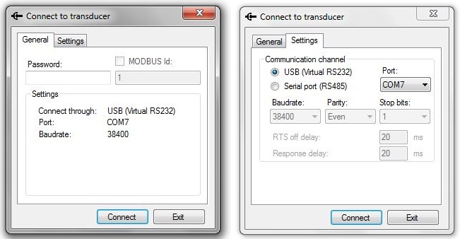
Figure 5. Setting up the communication parameters COM port, baud rate, parity, etc.
We cannot directly connect the measurement terminals to high-voltage transmission lines without damage. Potential and current transformers must be used. To configure the CT/PT ratio, click “input” in the left pane of the tree view. Suppose the transmission line PT ratio is 230 kV to 110.7 V and the CT from primary to secondary is 1200A to 1A. Select the measurement method like “4-wire system, 3-element”, enter to appropriate input and output transformer values, and then click the “Apply” button to apply changes to the equipment.
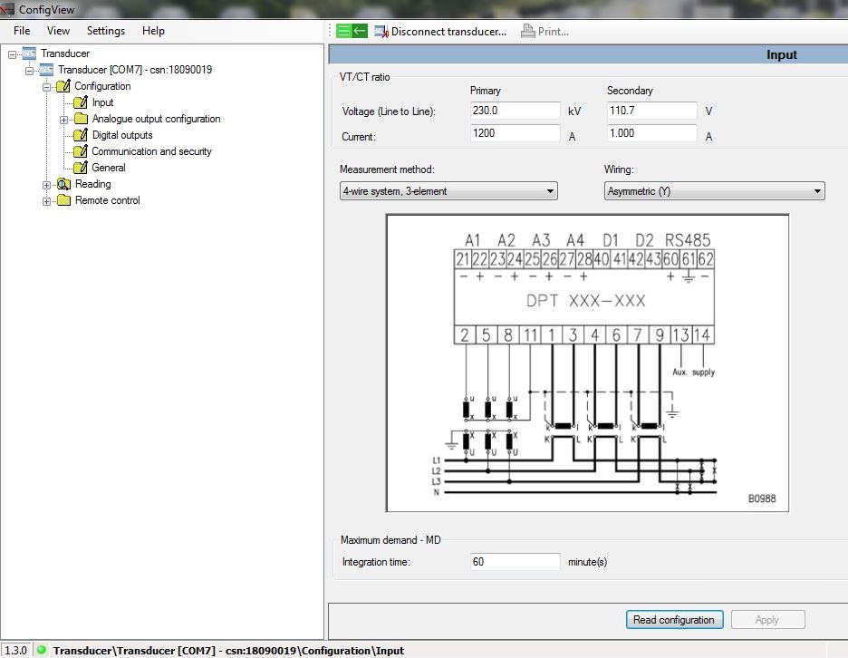
Figure 6. The wiring and PT/CT arrangement for high-voltage measurement.
Measuring the Active and Reactive Power
After setting the basic parameters like communication and primary and secondary (current/voltage) ratios, let's configure the two analog outputs for MW and MVAR.
To get ±10 mA signal values for the AI card, from the left pane, click “Analog output 1” and from the right pane, select the measurand “Active power” and enter the range from -595 MW to 595 MW with a matching respective transducer output in mA, from -10 mA to + 10 mA. Keep the other options as default. Perform the same steps for the “Reactive power” for “Analog output 2”.
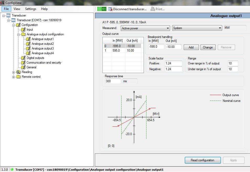
Figure 7. Setting analog output 1 for active power
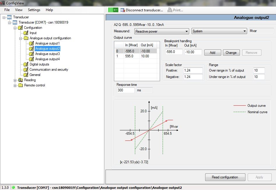
Figure 8. Setting analog output 2 for reactive power
The transducer also has two digital outputs that can be used for the pulse output. The pulse output can be used for energy import and export of transmission lines by setting the pulse constant and pulse length parameters.
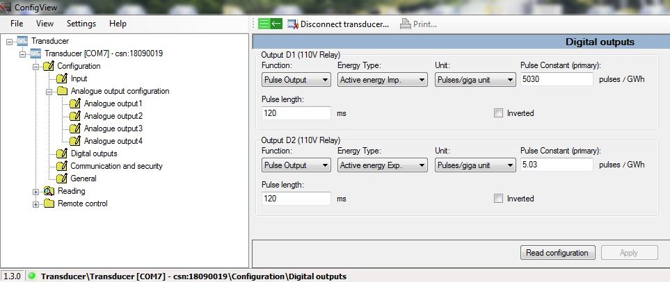
Figure 9. Configuring digital outputs of the transducer for energy import and export
The basic settings have been done in the lab and the transducer is now ready to be installed in the field. The same configurations can be saved as a file in XML format. Later on, the saved file can be restored on a new spare transducer in case of a malfunction in the installed active transducer.
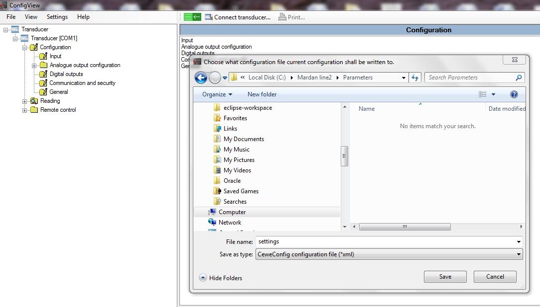
Figure 10. Saving the transducer settings for future replacement or expansion.
Transducers for Electrical Systems
The variety of transducers are part of the data acquisition system and are usually found in electric power plants, providing an interface to control systems for automation, measurement, signal conversion, and feedback for the controllers. Modern programmable transducers provide rich features by using dedicated software to connect the device to customize the parameters according to the requirement.
All images used courtesy of the author