 Facebook
 Google
 GitHub
 Linkedin
FANUC Robot Programming Example
FANUC robots, as with most other brands, are designed to be used in a wide variety of applications. Learn the common programming concepts and features along with an example of a motion program.
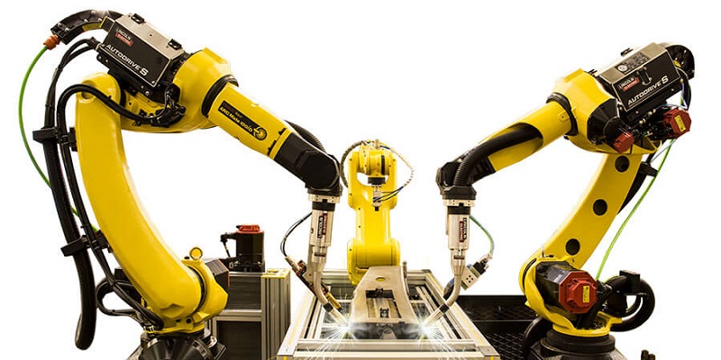
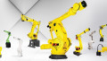
Figure 1. FANUC robots are often used in welding applications. Image used courtesy of FANUC
This article is a continuation of the robotic programming series.
Check out the previous articles:
Industrial Applications
Just like with the ABB robot, FANUC robots can be used in a wide variety of different applications. The six-axis articulating robots are the most popular style of robot in most industries because of the tool centerpoint (TCP) orientation ability and payload capacity. A common industrial application is to transfer parts from a conveyor to a dial table for welding. If the robot is also used to complete the weld, the tool is outfitted with a weld tip and follows a taught path for welding the components together. Below is a sample programming process for transfer of material to palletize or prepare a welding cell.
Registers
Within the FANUC teach pendant (TP) programming language, variables are not defined as in a typical programming language by selecting a boolean, integer, or float data type. Variables are referred to as registers, there are standard numeric registers, position registers, and a few others for specific purposes.
It is important to organize your registers and develop a convention on how to populate the registers so that they are grouped by function. Because these registers are in a tabular format, it may be helpful to use a spreadsheet program to organize your registers before you actually program the robot.
Registers allow for a comment description to be added, but screen space is limited so try to make the comment as small as possible. Always make sure you leave spare registers between various groups, since it may be necessary to go back and add registers if the program is edited later. This practice is also common in CNC G-codes.
Numeric Registers
These standard registers are simply integer values, useful for counting repetitions or storing geometric size numbers.
Numeric registers are stored in a table, so a logical convention should be used. For groups of commands like program select values, counters, offset values, or orientation data, it may be reasonable to break the registers up into functional groups 0-10, 10-20, etc.
Position Registers
These registers contain x,y,z, and orientation data, globally accessible to all programs and routines. For position registers, it may be helpful to use lower numbers for home, pounce, or clear of tooling positions. This way, it is easily recognized if the robot is going to a pounce position or a working position.
Flags
A flag is a type of I/O that is internal to the robot, not physically attached to an I/O port. They are boolean variables, containing only true or false. Typically, a flag would be used in gripper routines, in the pick and place routines for part tracking, or for tracking when a robot leaves / enters an area. Flags are stored in the same number ordered tables and require a similar approach to grouping the used flags by function.
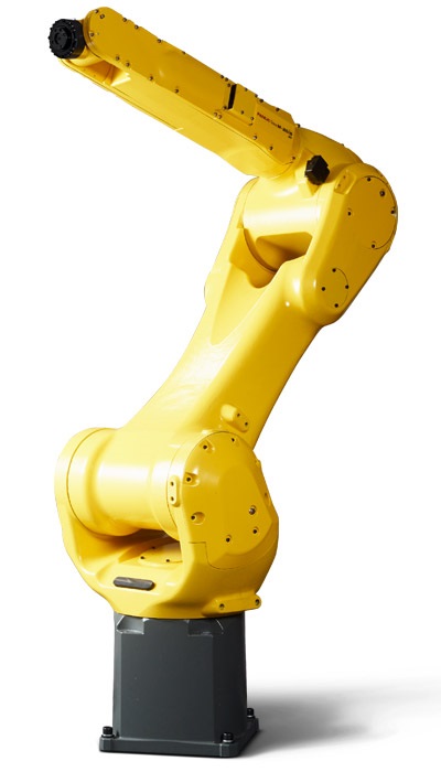
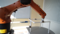
Figure 2. FANUC M20iB/25 with a 25 kg payload capacity and nearly 1900 mm reach. Image used courtesy of FANUC
Fieldbus I/O Mapping
The inputs and output of the robot with respect to the Fieldbus need to be mapped using another numbered table. Again, creating a logical structure is important.
Frames
A frame is a defined coordinate system used as a matter of convenience when the straight lines of an external conveyor, welding jig, or perhaps a machine chuck don’t line up with the robot base. There are three different frames available, tool frames, user frames, and jog frames. Each frame is stored in a numbered table and can be grouped by function similar to the registers. These frames are useful if the robot is working with an environment or end-of-arm tool that isn’t perfectly alighted with its own xyz coordinate system.
Tool and user frames can be changed between routines, so it is good practice to ensure proper frame selection at the beginning of each program, or unintended motion may occur. This is seen in the Motion Routine example below with UFRAME and UTOOL calls at the beginning.
Robot Routines
Once the registers, I/O, and frames are set up, you can then start building the robot routines that will call different robot functions and motion routines. The main routine handles the calls to different robot functions based on the integer value received from the PLC. Then use a different routine for each function. The goal with TP programming is to keep the routines compact, with each performing just one function. This may lead to more routines, but it is much easier to edit and debug each routine separately.
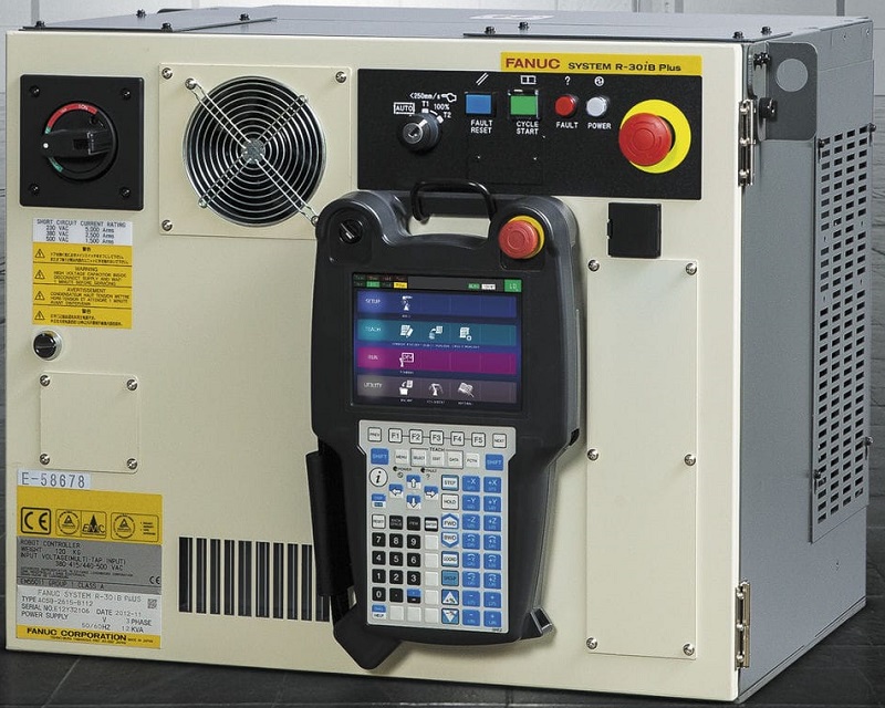
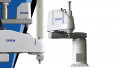
Figure 3. FANUC R-30iB Plus control cabinet. Image used courtesy of FANUC
Main Routine
The main routine is where we develop our main loop that calls the robot functions. In the following example program, we start with a call to an initialize routine that clears any handshakes or tracking variables.
After the initialize call, we check for a 0 command in register 1 to call a routine that captures a command from the PLC. This is used to jump to the appropriate label and call to a subroutine. After the motion routine is complete, we will set the active command to zero which will trigger a call to capture a new command from the PLC (in line 42). Faults can also be implemented if invalid commands are received.
In the FANUC TP language, a line beginning with ‘!’ indicates a comment line.
1: ! -------------------------------
2: ! Main Program
3: ! -------------------------------
4:
5: ! === Initialize =================
6: CALL INITIALIZE
7:
8: LBL[1:Loop]
9: ! === Get a PLC Command ==========
10: IF R[1:nCmd]=0,CALL GETNEWCMD
11:
12:
13:
14: ! -------------------------------
15: ! Check for pick tray commands
16: IF R[1:nCmd]>=11000 AND R[1:nCmd]<12000,JMP LBL[1100]
17: IF R[1:nCmd]>=12000 AND R[1:nCmd]<13000,JMP LBL[1200]
18: ! -------------------------------
19: ! Check for other commands
20: SELECT R[1:nCmd]=1,CALL MHOME
21: =2,CALL MSERVICE
22: =11,CALL MPLACEDIAL
23: ELSE,JMP LBL[9998]
24: JMP LBL[9000]
25: ! -------------------------------
26: LBL[1100:Tray1]
27: CALL MPICKTRAY(1)
28: JMP LBL[9000]
29: ! -------------------------------
30: LBL[1200:Tray2]
31: CALL MPICKTRAY(2)
32: JMP LBL[9000]
33: ! -------------------------------
34: LBL[9000:Command Complete]
35: TIMER[1]=STOP
36: JMP LBL[1]
37:
38: ! ============================
39: ! Invalid Command Number
40: LBL[9998:Fault]
41: TIMER[1]=STOP
42: R[1:nCmd]=0
43: R[3:nFaultNum]=11
44: CALL SETFAULT
45: IF R[3:nFaultNum]=0,JMP LBL[1]
46: JMP LBL[9998]
47:
48: ! === End ========================
Motion Routines
At the top of the motion routine, make sure to set the tool and user frames, verify parts present, and set the gripper position. Call any routines that might calculate required position offsets that can adjust the exact data inside a position register (such as in lines 37 and 38). Once any appropriate adjustments are calculated, the actual positional moves can be completed. Line 41 shows an example of a linear move, while line 69 illustrates a joint move.
1: ! -------------------------------
2: ! Pick Program
3: ! AR[1]=Tray Number
4: ! -------------------------------
5:
6: UTOOL_NUM=1
7: UFRAME_NUM=0
8:
9: F[4:bPartMissingFlag]=(OFF)
10: ! Turn Vacuum Outputs OFF
11: DO[16:Close Grip Hs (Pulse)]=OFF
12: DO[17:Open Grip Hs (Pulse)]=PULSE,0.2sec
13:
14: ! Set UFrame and Current Nest Pos
15: IF AR[1]=1,JMP LBL[10]
16: IF AR[1]=2,JMP LBL[20]
17:
18: LBL[10]
19: R[19:nCurrUFrame]=2
20: ! Calculate Current Tray Nest Pos
21: CALL CALCTRAYNESTPOSN(4,R[10:nNest])
22: PR[12:pCurr]=PR[102:Scratch]
23: JMP LBL[30]
24:
25: LBL[20]
26: R[19:nCurrUFrame]=3
27: ! Calculate Current Tray Nest Pos
28: CALL CALCTRAYNESTPOSN(5,R[10:nNest])
29: PR[12:pCurr]=PR[102:Scratch]
30: JMP LBL[30]
31:
32: LBL[30]
33: CALL CHKPARTPRESFAULT
34:
35: ! Pick PCBA from Tray x
36: ! Setup Offsets
37: PR[101,1:Scratch]=0
38: PR[101,2:Scratch]=0
39: PR[101,3:Scratch]=R[30:nTCZoff]
40: OFFSET CONDITION PR[101:Scratch],UFRAME[R[19]]
41:L PR[10:pCurrNest] R[60:MaxSpd_mm\s]mm/sec CNT25 Offset
42:
43: ! Time Before(TB) used to
44: ! close grippers while moving
45:L PR[10:pCurrNest] R[62:PnPSpd_mm\s]mm/sec FINE TB R[50]sec,CALL CLSRGRIPTRAP
46: ! Ensure closed
47: CALL CLSGRIPTRAYPOSN
48:
49: ! Move to Tray Clear Position
50: ! Distance Before(DB) used to
51: ! check part presents moving
52:L PR[10:pCurrNest] R[126:MaxSpd_mm\s]mm/sec CNT50 Offset DB R[52]mm,CALL PICKHSSIGTRAP
53:
54: ! Move to Dial Nest 1 Clear
55: ! Setup Offsets
56: PR[101,1:Scratch]=0
57: PR[101,2:Scratch]=0
58: PR[101,3:Scratch]=R[31:nDCZoff]
59: OFFSET CONDITION PR[101:Scratch],UFRAME[1]
60:L PR[3:pDialNestRef] R[60:MaxSpd_mm\s]mm/sec CNT100 Offset
61:
62: ! If part missing move to good position
63: ! to open gripper
64: UTOOL_NUM=1
65: UFRAME_NUM=0
66: IF (F[4:bPartMissingFlag]=ON),JMP LBL[40]
67: CALL GETNEWCMD
68: IF R[1:nCmd]=11,JMP LBL[9999]
69:J PR[1:pHome] R[60:MaxSpd_mm\s]% CNT100
70: JMP LBL[9999]
71:
72: LBL[40]
73:L PR[6:pClrToOpn] R[60:MaxSpd_mm\s]mm/sec FINE
74: DO[16:Close Grip Hs (Pulse)]=OFF
75: DO[17:Open Grip Hs (Pulse)]=PULSE,0.2sec
76: WAIT .30(sec)
77:J PR[1:pHome] R[60:MaxSpd_mm\s]% CNT50
78: CALL SETCMDDONE
79: JMP LBL[9999]
80:
81: ! === Error Description Here==
82: LBL[9998]
83: R[3:nFaultNum]=XX
84: CALL SetFault
85: IF R[3:nFaultNum]=0,JMP LBL[9999]
86: JMP LBL[9998]
87:
88: ! === End ========================
89: LBL[9999]
90: F[4:bPartMissingFlag]=(OFF)
Conclusion
Although this is one example, all programmers will have different tricks to create programs that are suitable for each situation. Always make sure that the robot can recover back to home or a safe position and send faults data to operators immediately. Try to keep routines focused on one action or function, this makes troubleshooting easier and your code easier to read. Programming robots can be personal and creative, learn to use the features of the software and have fun!
If you have experience with programming these robots, and you have discovered helpful tips and tricks to increase efficiency and troubleshooting, please share in the comments below!


The section under the Fieldbus I/O Mapping heading seems to be cut off. What does the rest of the section say?