Facebook
 Google
 GitHub
 Linkedin
Fuel Cell HIL Simulation and HMI Control Techniques
New control technology requires new interfaces. How can you implement fuel cell hardware-in-the-loop (HIL) simulations using an HMI?
Human-machine interfaces (HMIs) have long been providing a way for humans to interact with machinery. As new control technology evolves, new interfaces are developed, including intuitive, easy-to-use HMIs for complex hardware-in-the-loop (HIL) fuel cell simulations.
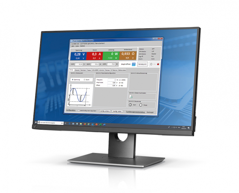
Figure 1. HMIs make it easier to implement fuel cell simulations and tests that make use of bidirectional DC power supplies and regenerative DC loads. Image used courtesy of EA Elektro-Automatik
Fuel Cell HIL Simulation Using Power Supplies and DC Loads
One particular approach to fuel cell HIL simulation taken by companies such as Elektro-Automatik and Regatron involves replacing either the fuel cell itself or the fuel cell load with bidirectional DC power supplies or regenerative DC loads to perform simulations for tasks such as fuel cell stack and system functional testing.
Overall Goal of HMI Control
Most engineers are familiar with GUIs, also called graphical user interfaces, and interact with them daily. They have become a familiar sight on everything from laptops to self-checkout modules at stores. Pre-dating the concept of a GUI is the HMI, which stands for human-machine interface.
The purpose of a general HMI is to allow humans to safely and efficiently interact with a machine. HMIs range from electrical and mechanical devices such as physical switches, dial readouts, and lights, to full GUIs, but their purposes are all basically the same.
In an industrial setting, GUI-based HMIs are often used with the control systems that drive modern automation. However, that is not their only application. HMIs are also used with the fuel cell HIL simulation, and physical testing alluded to in the previous section.
In the context of the fuel cell simulations, HMI control aims to do the following:
- Allow engineers to interact with the simulation in an intuitive way
- Provide real-time feedback that is visual as well as numerical
- Reduce mistakes during the process of simulation and testing
- Save time in the design and testing phase of product development
Examples of HMI Control in Fuel Cell HIL Simulation
HMIs can also make it easier to import and export critical data. Depending on what is being simulated, HMIs can allow users to define a target resistance for the programmable DC load to set the desired current to be drawn from the fuel cell stack. The resistance of the programmable load can then be configured to change over time or based on user interaction through an HMI to simulate varying load conditions.
The adjustment of the settings involved and monitoring of the simulation is made much easier by using an HMI such as the one shown below. Note the combination of buttons, dials, and text boxes that make the interface intuitive to use.
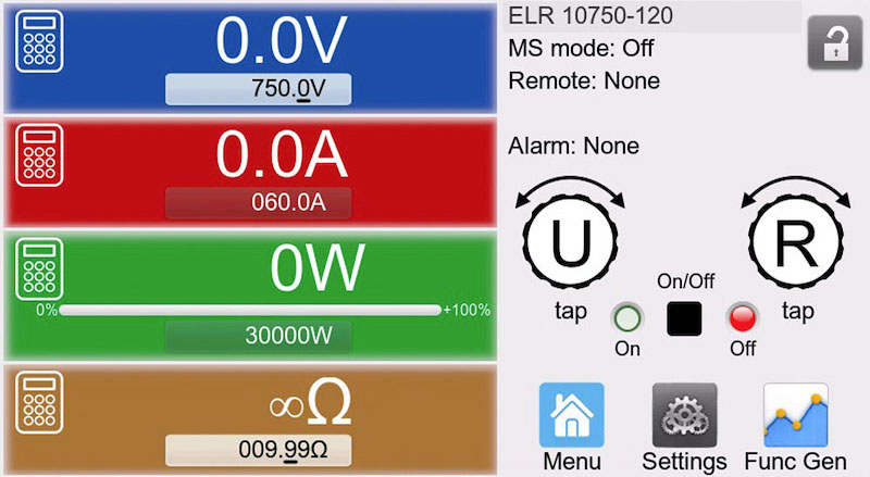
Figure 2. Example of an HMI for simulating contact resistance. Image used courtesy of EA Elektro-Automatik
Drawing further from this particular HIL simulation package, we can see that once an appropriate resistive load has been selected, the HMI can control (start and stop) and observe the fuel cell behavior based on a defined fuel cell curve. Control of the power supply and load occurs through the interface with start and stop buttons whose purpose can be determined at a glance (green right-pointing arrowhead for go, square for stop).
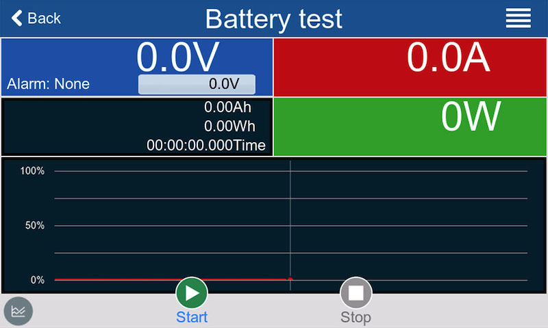
Figure 3. Example of an HMI used to start, stop, and monitor fuel cell behavior according to a defined fuel cell curve. Image used courtesy of EA Elektro-Automatik
Another more extensive HIL simulation control HMI is shown in the next figure. All the necessary parameters can be set and the output viewed through this one interface. Additional performance can be visualized through graphs with a click of the open graph button seen at the far left, top corner. Input parameters, such as those for defining the fuel cell graph, can easily be verified using both numbers and a plot of the chart.
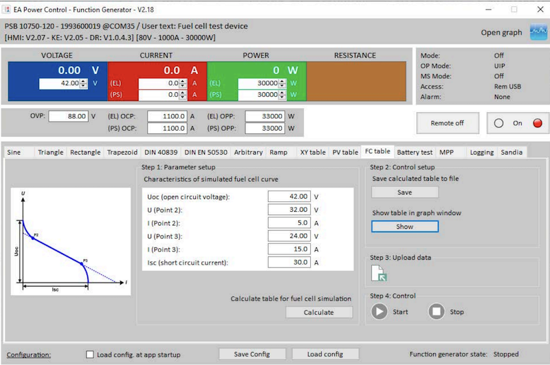
Figure 4. Main HMI for a fuel cell simulation. Image used courtesy of EA Elektro-Automatik [PDF]
Below is a similar HMI from a similar simulation package that also supports verification of input parameters and control of the HIL simulation from one HMI control screen. Note that the top row makes use of output resembling a traditional red-on-black LED readout.
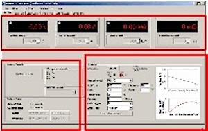
Figure 5. Main HMI for an energy flow fuel cell simulation software. Image used courtesy of Regatron
Benefits and Challenges of HMI Control
In general, HMI control has several benefits in various control applications including the following:
- Increased efficiency through intuitive design and easy access to control parameters
- Compact size as the multiple screens that HMI’s support can display as much data and feedback as required
- Better diagnostics and easier troubleshooting due to the amount of information provided by a well-designed HMI
In addition, there are other benefits more specific to the context of fuel cell HIL simulation:
- HMIs, rather than direct manual control, support the integrity of the simulation
- Selective access to key parameters
- Setup is less complex for well designed HMIs, reducing the time involved for setting up simulation and testing
- Provides real-time graphical and numerical feedback during testing
- Eliminates the need for directly programming the associated hardware
There are challenges to HMI control for simulations as well. For example, HMI standards developed and updated by the International Society of Automation (ISA) may eventually include simulations such as those discussed.
This may involve the need for updated software. While maintenance is more often associated with mechanical/electrical HMIs, they are also important when simulation software is involved. Software and firmware updates are necessary for system performance, reliability, and security.
The main challenges related to HMI control for fuel cell simulations lie with the simulation developer. There is still an abundance of programming involved that lies behind the intuitive HMI. It is no small task to integrate hardware with a control system for HIL simulation, much less program the simulation framework.
Engineers can use different tools such as Simulink or LabVIEW, and while they may simplify some aspects of simulation, they still require in-depth knowledge to use these tools properly. The design of the GUI for the HMI requires its own set of skills to ensure it is intuitive, easy to use, and easy to interpret.
The use of bidirectional DC power supplies and regenerative DC loads to perform reliable, accurate fuel cell HIL simulations requires HMI control to be efficient and effective. When HMI controls are used wisely, they offer several benefits over non-HMI approaches and can significantly reduce the time involved in the simulation and testing of fuel cells.