Facebook
 Google
 GitHub
 Linkedin
How-to: Programming Discrete I/O With a Koyo DirectLOGIC PLC
Learn how to use DirectSOFT6 to program discrete I/O functions in a Koyo DirectLOGIC PLC. Although these PLCs are older, they are found in many existing automation installations.
Programming and using PLCs is one of the most fun parts of being a control system engineer. Designing the local program flow, wiring the I/O devices, and finally, watching the successful operation of a system that you designed!
Getting started with a new PLC can be intimidating, but there are many similarities between various makes and models, allowing a transfer of most of your skills from one platform to another. If you have found yourself faced with a DirectLOGIC PLC from Koyo, read along to learn how to connect to the PLC with a serial port and download a simple program to read and respond to I/O instructions.
DirectLOGIC PLCs from Koyo
Going back a few decades, Koyo Electronics was a company that constructed high-quality PLCs including the DirectLOGIC series. In the mid 1990’s, AutomationDirect was formed as a subsidiary of Koyo Electronics to focus on improvements to the PLC market and the various product lines.
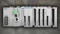
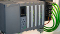
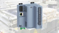
The DirectLOGIC series is one of the more popular PLCs to have existed in the market, and it includes both small brick-style models with fixed I/O, as well as modular expandable units.
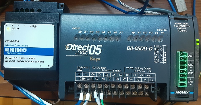
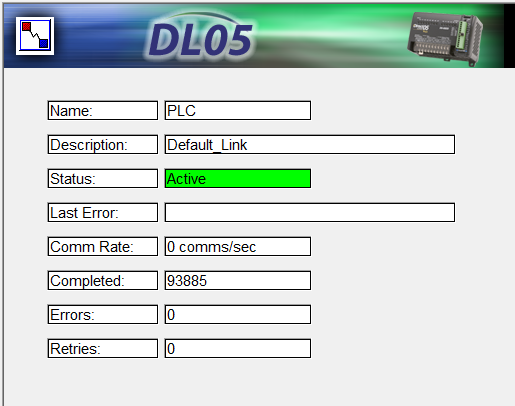
In this tutorial, we will use a DL05, a compact model with 8 digital inputs and 6 digital outputs, plus one slot for expansion I/O.
Connecting With DirectSOFT6
The first step is connecting to the PLC. We will be using the DirectSOFT software, of which a limited version is free; we’re limited to 100 words of logic, more than sufficient for any demonstration project.
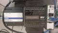
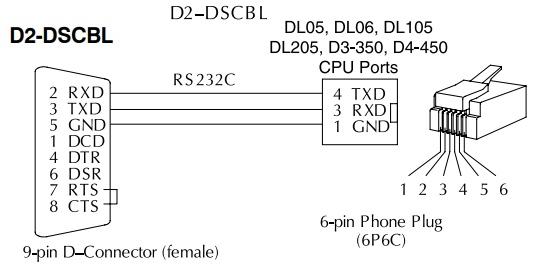
My laptop does not have a serial port, so I use a standard USB-to-serial converter and a 6P6C RJ12 serial cable for the connection. The proper cables and pinouts are shown in the technical documentation. It is recommended to purchase the right cable, but in my case, I have created my own cable that works perfectly.
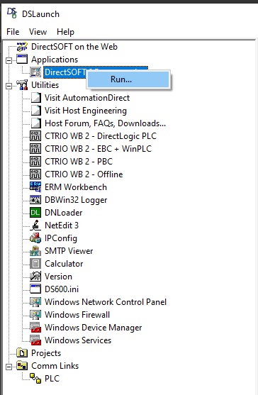
Download and install the software, and we can access the ‘DSLaunch’ application which begins the communication setup.
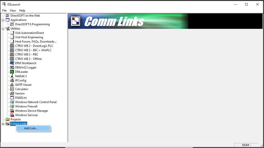
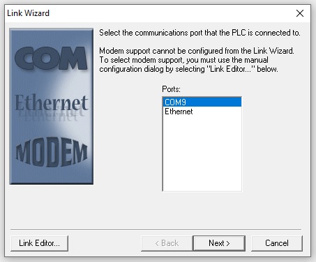
Select the ‘Comm Links’ tab, right-click and ‘Add Link…’ The link wizard will now guide us through the communication setup process. We must connect through the serial COM port, as an Ethernet port is not available on this PLC.
What if the Port Is Not Visible?
If a COM port does not appear (as is shown below), check ‘Device Manager’ and verify that there is a COM port. If not, try a new USB-to-serial converter.
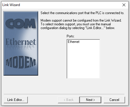
This happened during my first trial connection. I have several generic USB-to-serial converters, and although the device driver software appeared to install correctly, Device Manager did not report a new COM port.
Using a new converter cable solved the issue immediately.
After choosing the correct COM port and proceeding, the software will attempt to communicate with the PLC, choosing various aud rate and parity settings. It should successfully settle on the proper settings.
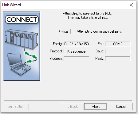
What if the Communication Errors Out?
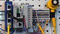
If, after cycling through all of the settings, the software cannot find the PLC, first be sure that it is powered on, and that the serial cable is plugged into PORT1 on the PLC.
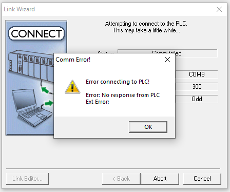
After this, the serial cable may be suspect. In an early attempt, I was using a standard serial cable with the 6P6C RJ45, but it had the wrong pinout.
Using my old homemade cable, the issue was immediately resolved.
After solving any communication problems, we should now have a valid connection with the PLC.
DirectSOFT Programming Interface
Once the com link has been established, we can move on to creating a simple ladder logic program.
Open the programming interface by running the ‘DirectSOFT Programming’ application in the launcher.
We’ll first need to enter ‘Edit’ mode to create a program. This can be done with the icon on the right side, or from the ‘Edit’ menu, or Ctrl-E.
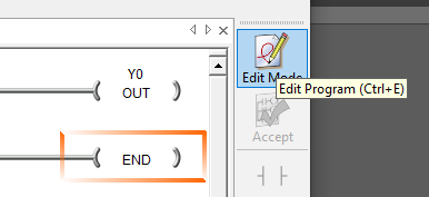
With the Editing mode active, we simply need to place a normally open contact and a standard output coil into the first rung.
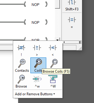
F2 will insert a new normally open contact and F5 will open up the menu for choosing a new output coil. The quick menu at the right side can easily be customized with the ‘Add or Remove Buttons’ in the menu above.
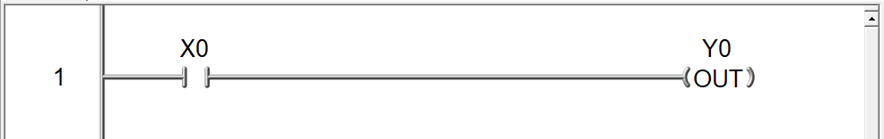
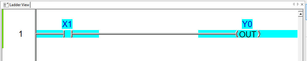
The addresses for the embedded I/O points are quite simple. X denotes the input addresses and Y denotes the output addresses. This program will use the first input terminal to energize the first output terminal - the classic ‘Hello World’ program for PLC engineers!
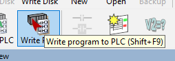
The ‘Write Program’ button loads the ladder logic from the computer into the PLC.
Any programmer with experience will realize that it’s important to monitor the live status of each coil and contact while the programming is running. That way, we can avoid costly troubleshooting time by immediately differentiating between programming and wiring problems.
The ‘Status’ button will toggle the live monitor view with blue highlights any time the instruction is true.
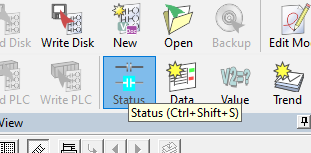
With the ‘Status’ button active, the instructions will illuminate as you press the button wired to the input terminal.
What’s Next?
Once you have developed the fundamental knowledge of how to design and download programs, experiment with more complex instructions and multi-rung layouts. In no time, you’ll be an expert in DirectLOGIC PLC programming!
All images used courtesy of the author
We have plenty of other PLC and microcontroller tutorials, get some inspiration from a few more!
- Intro to Siemens S7-1200 PLC and TIA Portal Programming
- Intro to PLC Programming with Rockwell’s Studio 5000 and CompactLogix
- How To: Simple Programming with AutomationDirect Productivity PLCs
- Ladder Logic for the Arduino Opta PLC: Creating Your First Program
- Turn a Raspberry Pi Into a PLC Using OpenPLC