Facebook
 Google
 GitHub
 Linkedin
How To Read Ladder Logic in PLC and Relay Controls, Part 1: Inputs
Ladder logic is an industrial control systems legend stemming from electrical line diagrams before the days of PLCs. Although logical, they are difficult to interpret.
Ladder logic is one of the oldest forms of electrical “programming,” found inside nearly every controller in existence, so it’s essential to understand. Here are a few of the simplest tricks and tips to read and interpret the meaning behind the lines and symbols.
Electrical Origins of Ladder Logic
Electricity 101: in order to complete a circuit, there must be a continuous conductive path between both terminals of a power supply.
This is both an oversimplification and, at the same time, the best advice you can be given to read ladder logic.
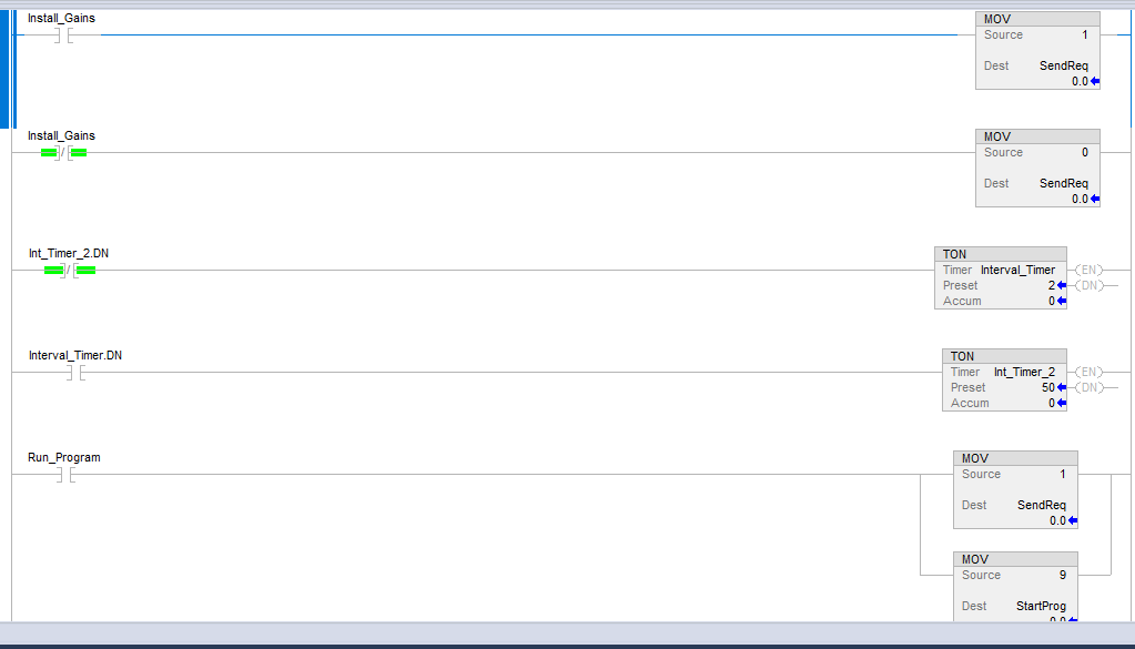
Figure 1. Most ladder logic consists of many relatively simple lines of logic; therefore, it seems more complicated than it should be.
Ladder logic began as a method of drawing circuit schematics with fewer lines. The relays that were used to drive control systems before computers were interlaced with the same voltage, usually 120 vAC or 24 vDC, supplying the coils of some relays, the contacts of others, and often both coils and contacts in various patterns. To simplify the drawings, the power supply itself was ignored (always assumed to be present), and the left and right sides of the page represented the + and - of the supply, respectively. For an AC supply, this would mean the L and N occupy the left and right.
Always Left to Right
Imagine the lines as the conductive paths for electricity. Inside a digital ladder diagram (LD) program, these lines aren’t literally electrical conductors, but that’s exactly what they represent in the schematics.
Start reading at the far left-hand vertical line. Every rung (line) receives electricity from the power supply in a real-life circuit, and likewise, every rung in the main routine of an LD program will be examined. Not every rung will allow electricity/logic to flow through to the outputs, but they still must be examined.
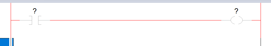
Figure 2. A blank line of logic with a single input and output instruction.
Starting with the left-hand end of the first rung, trace along the line to the right until you encounter one of two things: either some sort of symbol blocks the path, or there is a branch in the line where another line drops down vertically, then also progresses to the right.
Encountering a Logical Instruction
In most ladder lines, the very first instruction takes the form of a discrete ‘contact’ or perhaps a function block that requires multiple inputs.
Discrete Contact Commands
Think of any discrete contact as a simple pushbutton: it’s either pressed or not pressed, nothing in between. As far as the computer is concerned, it doesn’t care what real-world device is out there: limit switch, button, optical sensor, relay contact, motor aux contact, whatever. All it cares about is that some incoming piece of information from that one screw terminal is either “true” or “not true.” (After all, it’s the electrician’s job to make sure that screw terminal is connected to the right device!)
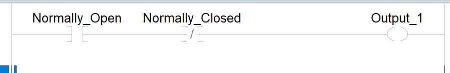
Figure 3. At the far left, an NO (XIC) symbol is followed by an NC (XIO) symbol. These symbols are universal.
There are two kinds of contacts, most often referred to as normally open and normally closed (NO and NC). Some companies prefer not to use this notation since a novice might be confused when they see an NO command in the program but then learn it’s an NC switch in real life.
Don't be confused: the type of command used in the program does not reflect what kind of real-world switch is being used.
This is actually one of the greatest things about ladder diagram programming. You can wire up an entire facility with nothing but normally open switches and contacts, then customize the program to treat them as if they were NO or NC any time the program requires such logic. Program adjustments don’t need a hardware replacement like they did back in the days of relay logic.
To better understand the concept, think of the two commands in this manner.
- If you see an NO (sometimes called XIC) command, it means that if electricity flows in the real-world circuit, the command will be True.
- If you see an NC (sometimes called XIO) command, it means that if electricity is blocked in the real-world circuit, the command will be True.
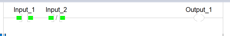
Figure 4. Even with no knowledge of real-world devices, the highlights tell me for certain that “electricity is flowing through input 1” and “electricity is not flowing through input 2.”
In my experience, I have seen all kinds of tables and charts that outline all possible conditions and scenarios for the real-world device, its state, and the comparable logic for each one, but that can be a terrible chart to try and memorize.
The key is to simplify the whole thing. Just remember what makes a command become true. That’s it. If you can remember this, I guarantee you can figure out what makes a command become false. From there, you can go find the real-world device and decipher what makes it block or flow electricity. But remember, keep it simple!
Function Block Commands
Function blocks are rectangular commands with input lines on the left and output lines on the right. They can perform advanced commands like timing, counting, math, and anything else that isn’t just ON/OFF.
For most of these blocks, there will be one continuous line from the left end of the rung. This is the “enable” input. If the path is false (blocked), the command is disabled. If there are no instructions between the left side and the function block, that means it is constantly being evaluated by the program.
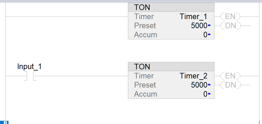
Figure 5. Two timers. The top one is not useful: there is no input condition before the timer. It will run as soon as the controller is energized and will never stop. The second timer has an appropriate input condition.
Most function blocks also have additional inputs that do not extend all the way to the left-hand side. These don’t enable or disable the command but perform specific tasks, like resetting a counter, etc.
To understand these, you must look into the documentation for each language, like a help file, that describes each command. They can be tricky but still consistent and manageable!
Encountering a Branch (Sub-Rung)
You are bound to discover a branching rung, usually following a command, but sometimes, it’s the first thing in a rung. Just like electricity, logic can take two paths at the same time. If you run into a branch, just continue in a straight line first and examine the instructions in that main branch. Once you come to the end of the rung or a blocked (false) instruction, you can go back to the branch and evaluate the secondary rung.
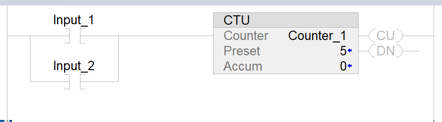
Figure 6. A very simple branch (sub-rung) is encountered immediately, and either Inputs 1 or 2 can energize this counter.
Again, for the sake of simplicity, do NOT try to evaluate a main rung and multiple sub-rungs simultaneously; you will only confuse yourself.
Ladder Logic Pitfalls to Avoid
Next, we will discuss some common pitfalls and challenges in reading ladder logic diagrams.
All images are used courtesy of the author