Facebook
 Google
 GitHub
 Linkedin
Insulation Testing with Resistance Meters
Electrical resistance can be intentionally extremely high to insulate and stop current between conductors. Learn about measuring insulation using a mega-ohmmeter.

Electrical resistance usually exists under one of two categories. The first category is the ‘small’ range of resistances used in devices that regulate the amount of current allowed through control and load devices.
The second category is resistance, which is intentionally extremely high to insulate and stop current between conductors. Insulation can be difficult to measure with conventional multimeters, using mega ohm-meters or ‘meggers’ instead to determine proper insulative properties.

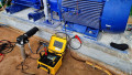
Figure 1. A technician uses a megohmmeter to test insulative properties. Image courtesy of AEMC.
It is difficult to argue over the definition of ‘high’ and ‘low’ values, since different fields may use entirely different scales of components in electrical terms. However, we can consider two general ranges of electrical resistance to describe a difference in testing methods.
A typical multimeter can be used for’ low’ resistances to obtain a reading, usually between Ohms and Mega-ohms. These directly relate to the amount of current allowed through a circuit.
For ‘large’ resistance values, a multimeter will show ‘OL’ or a variation of this notation, showing a resistance value larger than anything that can be displayed on the meter. Depending on the situation, this might be indicative of an open switch or broken wire. However, in other cases, this can be a measurable insulation resistance value. When the subject of insulation is indeed the component under test, it may not be good enough to use the relatively low range of a typical multimeter.
There is a family of test instruments designed to measure resistance into the billions of ohms or Giga-ohms far beyond the range of normal meters for testing insulation. These devices are called Insulation Multimeters, or MegaOhmmeters, or commonly ‘Meggers.’
How Does an Insulation Multimeter Work?
All resistance meters, even a typical DMM, work similarly. The instrument supplies a voltage that, using the test leads, is placed in a fixed internal resistor and the test load device. The second voltage drop of the load resistor can easily be found using the voltage drop of the internal resistor, and then the voltage divider principle can yield the resistance.
The voltage supplied by the test instrument is usually only a few volts coming from a 9-volt or a series of AA batteries inside. This is sufficient for small resistance loads, but cannot yield a measurable voltage if the load resistance is significantly higher than the internal resistance.
To compensate for this lack of measurable voltage, a simple solution would be to raise the supplied source voltage. This is exactly what a megger is designed to do: supply a large test voltage.
For older meggers, the method was a hand-crank generator that could build up a huge voltage, sometimes well above 1000 volts. For digital meters, the step-up is done with a DC-DC voltage converter. These can still yield a high voltage, although 1000 volts is usually about the largest typical voltage on a digital mega-ohmmeter.
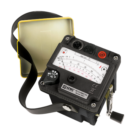
Figure 2. AEMC’s Megohmmeter Model 6501 is one example of a hand-cranked megohmmeter. Image courtesy of AEMC.
The voltage will rise in steady increments for normal digital mega-ohmmeters, starting with 50 or 100 volts, stepping up until a valid voltage drop is measured, providing a resistance calculation. If the voltage steps up to the highest level, still with no valid measurement, the display will show the maximum possible value. This may be a number, or a greater than (>) symbol, or on an analog display would simply peg the display to the maximum edge.
When are Megohmmeters Used?
The purpose of mega-ohmmeters is to test insulation resistance. Sometimes, they are rather called by the specific title ‘insulation multimeter.’ When a specific value of insulation must be present between conductors, or between a conductor and ground, this is the tool to utilize.
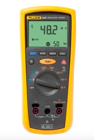
Figure 3. Fluke’s 1507 Insulation Resistance Tester. Image courtesy of Fluke.
Testing motor windings against the ground terminal is a very common use scenario. The insulation must provide protection to prevent the large winding voltage from pushing current through to ground.
The earth grounding path is meant to provide safety, not a path for current under normal operation. In fact, if the insulation becomes weak at a particular spot, it would cause one of the coils to generate less energy than the others, which would create vibration and uneven loading of the motor. This could provide additional damage to the mechanical equipment.
Testing the insulation between conductors in a cable is also a use for these meters. The insulation should provide extremely high resistance, even for low-voltage cables. If the wire path becomes very long or if the cable becomes slightly damaged, it may be indicated by a lowered (yet still very high) resistance.
Most often, there is no specific value that should be reported for either of the above cases. Very rarely does a datasheet provide an exact target resistance value, but rather a threshold safe voltage level. It is important to understand what the resistance value should be by testing a device in known working order or by obtaining a recording upon initial installation. After that, the resistance can be monitored in case of suspect failure. If the resistance has significantly lowered, it may certainly be considered a possible reason for the failure.