Facebook
 Google
 GitHub
 Linkedin
Math and Comparison Commands In Mitsubishi’s FX and Q Series PLCs
Mathematical operations are essential in PLC programming as they help in creating an argument output that is based on proportionality and numbers. Learn how to implement mathematical operations in FX and Q Series PLCs.
Mitsubishi Electric’s popular PLC lineup includes the Q and FX series PLCs. In this tutorial, we are going to delve deeply into some of the mathematics and comparison operations and how they can be used. We are also going to look at how we can manipulate data within ladder logic programming.
We will use examples from GX Developer or GX Works 2 software.
MOV Instruction for Data Manipulation
The move (MOV) instruction is a PLC programming command that is used to move data into or between registers. The syntax for moving data is; -[MOV S D]-, where S represents a bit device or a data device and D is the data register where the data is to be moved. Consider the ladder diagram example below. From the ladder diagram, M8011 is a special normally on contact. The constant value 10, denoted by the prefix K, is moved to D2.
In Mitsubishi PLCs, data is stored in data registers, which are denoted with ‘D’. These registers store numerical values that can be manipulated to fit the programming needs. In our case, we are going to use the data stored in the registers to perform mathematical operations.
These data registers can store any variable information, including integers, double integers, and floating-point values.
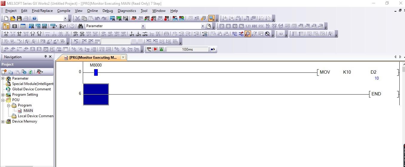
Figure 1. MOV instruction to move the variable 10 to D2.
SUB, ADD, and MUL instructions
To manipulate numerical data, we can either multiply, subtract or add. In Mitsubishi FX and Q series, SUB instruction is used to find the difference between values, SUM is used in the addition of values, and MUL is used to perform the multiplication of data values.
Consider the ladder program in the figure below. In the ladder diagram, a value K10 is moved to data register D2 in the first line.
The SUB instruction is used to subtract the values of D2 and move the results to D5 (0).
The ADD instruction is used to add the values in D2 and move the results to D6 (20).
Finally, MUL has been used to multiply values of D2 together and move the results to D7 (100).
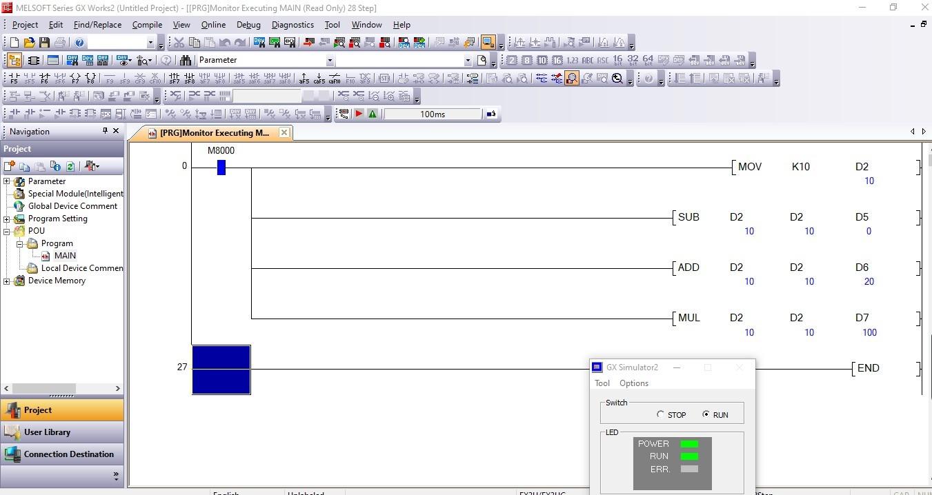
Figure 2. SUB, ADD/SUM, and MUL instruction ladder examples
Comparison instructions (<, =, >)
In FX and Q series PLCs, greater than (>), less than (<), and equal to (=) are used to create a comparator program. If the comparing conditions are true, the output of the ladder program becomes also true and turns on. If the comparisons are false, the output is off. The syntax of writing this instruction in a ladder logic program starts with the comparator and the 2-bit devices to be compared.
Note that comparison instructions are used as an input condition on the left side of a ladder logic rung, while math instructions are outputs on the right side, only performed if the input conditions of the run permit.
Consider the ladder logic diagram in Figure 3. IAs determined by the previous math operation, the values of data in data registers D5, D6, and D7 are 0, 20, and 100, respectively.
Using comparators, our simulated output relays M1, M2, and M3 are only ON when the conditions are true.
From the ladder example in the figure below, M1 and M2 are ON because the conditions of the values in the data register being compared, (D5 < D6) and (D7 > D6), are true.
M3 is OFF because the values of D5 and D7 are not equal.
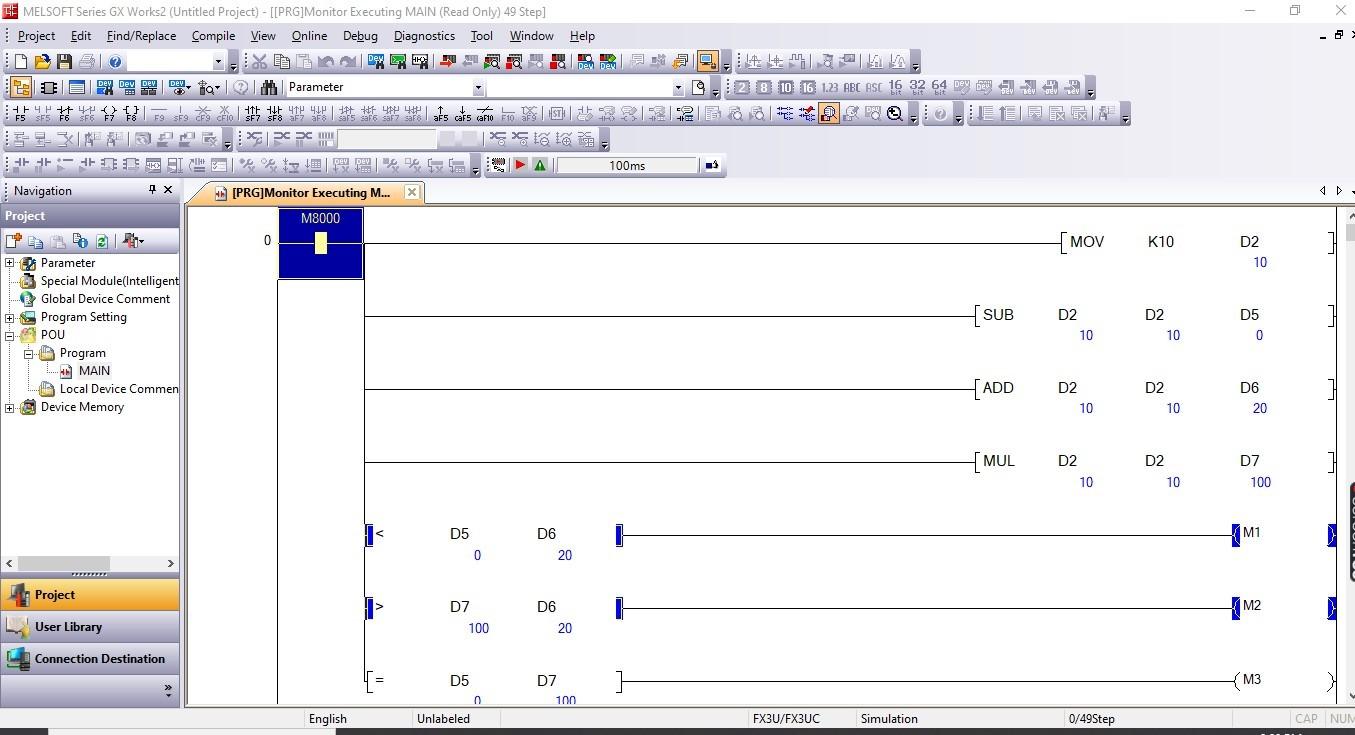
Figure 3. Ladder logic example of how the comparison instructions are used to control the conditions of outputs M1, M2, and M3
There are cases where an output requires two conditions to be true to turn ON. In such cases, ‘equal to or less than’ (=< ), and ‘greater than or equal to’ ( >=) are commonly used. In the syntax of the program, the application instruction starts with the symbols <= or >= then followed by the bit devices to be compared.
Combining Two Conditions
When conditions must be combined in order to compare multiple sets of inputs at the same time, they can be combined in series or parallel rungs to create AND and OR conditions, just like any arrangement of input conditions in a ladder diagram.
To better understand this, consider an example with series conditions (D10>D11) followed by (D12
Application Instructions in Mathematical Manipulation
Understanding these application instructions is essential in mathematical manipulation in Mitsubishi’s FX and Q series PLC. As an automation engineer or a programming enthusiast, having this knowledge brings solutions to programming challenges. Follow this guide if you want to get started with these application mathematical instructions.
Happy programming!
Check this PLC programming worksheet to test your ladder diagram knowledge.