Facebook
 Google
 GitHub
 Linkedin
PLC With a Miniature Twist: Crouzet Millenium Slim Tutorial
One of the smallest PLCs on the market, the Millenium Slim by Crouzet, can handle advanced functions with a wireless interface and function block (FBD) style IEC 61131 programming.
Controllers are getting smaller, thanks to exponential advancements in the capabilities of semiconductors. You don’t need a large IC to handle a lot of computing. In a modern controller, the bulk of the real estate is actually consumed with connectors for the real-world I/O devices and power. If the application doesn’t call for a large number of local I/O points, we can use a much smaller PLC, and that’s exactly what Crouzet has introduced with the Millenium Slim, claimed to be the smallest PLC ever.
Intro to the Small PLC
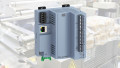
The Millenium Slim is designed to take up a very small slice of a DIN rail, measuring in with a width of only 17.5 mm (less than 3/4 of an inch). Along with that narrow spec comes a limit to the number of local I/O connections, with 4x inputs that can be configured as either digital or analog (with high-speed and PWM options available for various points) and 4x outputs that are either 6-amp relays or 0.5-amp transistors, depending on the model.
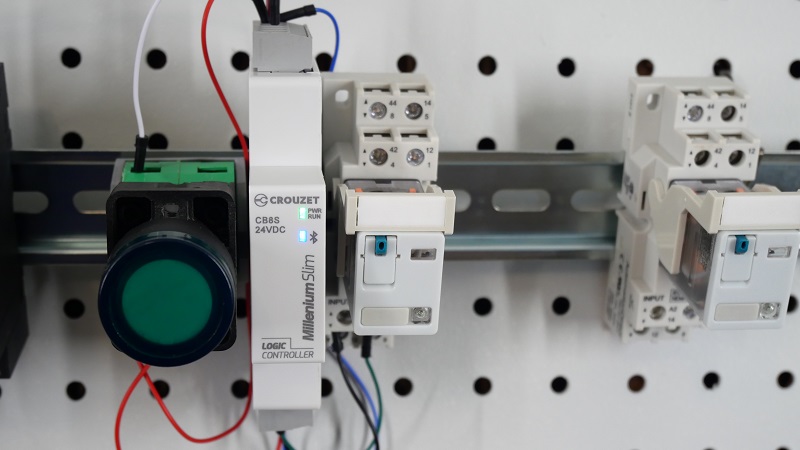
Figure 1. A Crouzet Millenium Slim with one digital input (pushbutton) and one digital output (relay).
Another question surrounding ultra-small controllers is the not-so-simple matter of communication ports. In the age of cyber security, it’s not as simple as finding the easiest connection; it must physically fit the space, be digitally capable of handling data rate, and utilize a security structure that prevents unauthorized access.
The Millenium Slim relies on Bluetooth connectivity for most networking functions. Connecting to a PC for program development, mobile monitoring devices, and other Slim devices for a large network all happen over Bluetooth. Interfacing with external devices happens through the built-in I/O terminals.
This PLC is not designed to replace a large, modular PLC. Crouzet offers other product lines for that operational scale, like the Millenium Evo and EM4, both with multiple network interfaces and expansion I/O modules available.
Getting Started With the Millenium Slim: Hardware
To begin a simple project, connect a DC power supply to the terminals labeled PS + and - (this is for the DC version; for AC inputs, they are labeled L and N).
The inputs are internally grounded to the negative (-) of the PS input, so you only need to supply a +24 volt signal to I1-I4 in order to energize an input. This makes testing a quick process, all you need is a single pushbutton from +24 v to I1.
Bluetooth is required, so your computer will either need a built-in BT adapter or a BT USB dongle, which are quite inexpensive from most major online sources.
CrouzetSoft Development Environment
The software for the Millenium Slim uses a function block environment, which accomplishes the same tasks as ladder logic. Still, it uses a different set of standard notations for inputs and outputs. Fortunately, many ladder logic commands are already in function block style (like timers and counters), so the differences are not too difficult to overcome.
Connecting to the Controller
As usual, the first step is establishing an online connection with the PLC. To begin, open CrouzetSoft and create a new project, choosing the series and model of PLC we are using. In my case, this is the DC supply version with transistor outputs (model # 88983902).
Go to Controller -> Configure Connections and select Bluetooth.
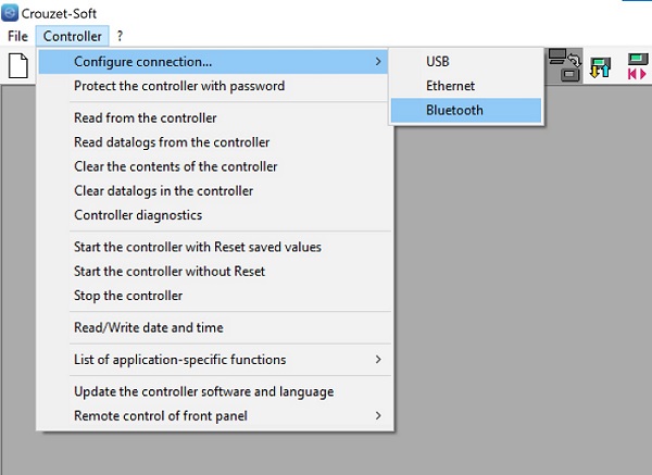
Figure 2. Bluetooth connection configuration.
Select the correct Bluetooth device (there will probably only be one) and click OK to connect to the controller.
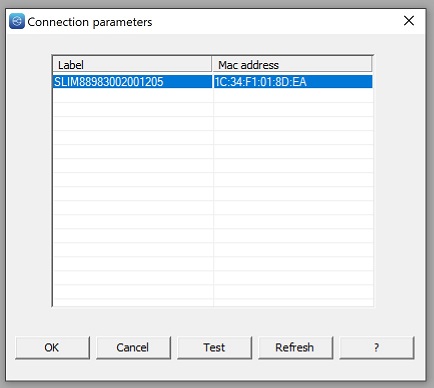
Figure 3. Bluetooth devices available.
Designing a Program
FBD may be a new language to some control engineers, but for those familiar with digital electronic circuit analysis, it will have a familiar feel.
Start with the basics: we want a discrete input to drive a discrete output.
In our ladder logic terms, we use NO and NC contacts (XIC and XIO), but in CrouzetSoft, these appear as a step input symbol from digital electronics, and in the command setup, we can choose between NO and NC.
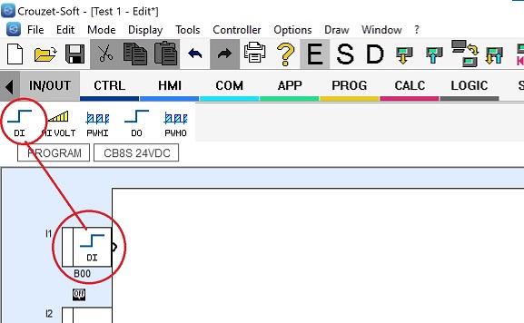
Figure 4. DI command added onto the first input slot.
Drag the step input, labeled DI, right into one of the inputs in the work area. In this dialog, we can actually choose a new icon based on the real-life input type, including switch contacts, limit switches, sensors, etc. Add a comment for clarity, and click OK.
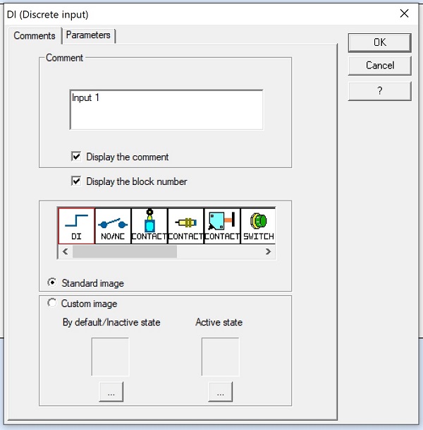
Figure 5. Digital input (DI) graphical and comment options.
Next, we can do exactly the same thing for the output. Click and drag a DO block to the output terminal. Similarly, we can choose a graphical image of the actual real-world output: fans, lights, LEDs, heaters, etc.
To join these two elements, click on the right edge of the DI block and drag all the way to the left edge of the DO block; a solid line will appear.
Downloading the Program
Since you are already online, you can select the icon with the blue arrow “Write.” You can choose to automatically start the controller after download. If you forget to check this box, Press the icon with the arrow at the top of the IDE.
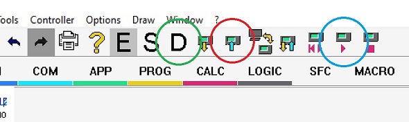
Figure 6. Download icons: Write (red), Start Controller (blue), and Debugging mode (green).
As a final step, we want to monitor the logic to be sure that it is actually working. The large letter “D” at the top stands for “Debugging” (“E” is for Edit mode, which you need to select before you can change the program).
Next Steps: Advanced Program
This project is simple, but the first steps are critical: connecting to the controller and downloading our first simple program.
Next, we’ll add actual control logic with multiple inputs and examine some of the analog input capabilities.
All images used courtesy of the author