Facebook
 Google
 GitHub
 Linkedin
Reversing the Rotation of an Industrial 3-Phase Motor
Many online sources explain how to reverse a 3-phase motor; this article will discuss the electrical principles that define why it works and how the phase relationships determine the rotation direction.
Reversing the rotation of 3-phase motors is a topic that’s referenced in virtually every online source that discusses motors.
The more complex methods include reversing circuits, inverters or programmable drives, or interlocked reversing starters. These techniques are used heavily throughout automated applications where the motor must regularly reverse directions, especially when careful speed control is important.
Reversing Rotation: The Simple Method
For a motor that only needs to operate in one direction, the most straightforward solution involves reversing two of the physical input wires coming from the power supply. In reality, this is exactly what’s happening inside those inverters and reversing starters, but it’s all hidden ‘under the hood.’
But how does this actually work? Why does reversing a couple of wires have such a major influence on a huge motor?
Always refer to the motor manufacturer's instructions to ensure you reverse the rotation properly. Not all motors have the same requirements, but most 3-phase motors operate under the same principles.
3-Phase Motor Fundamentals
Let's start by breaking down the main components inside a 3-phase motor. If you prefer a visual example of all the components inside a typical AC motor, you should check out this popular article on Control.com that shows a motor teardown.
For this article, we will focus only on the stator and the rotor.
- The stator is the stationary part of the motor that is composed of coils that create a rotating magnetic field inside the motor when supplied with an alternating current.
- The rotor is positioned in the center of the stator. It consists of ferrous cores (sometimes permanent magnets) that respond to the stator’s rotating magnetic field, forcing the rotor to spin.
To achieve rotation, both the stator and rotor are essential components. The stator generates a rotating electric field, which propels the ferrous elements on the rotor in the direction of the electric field, thus resulting in rotation.
Creating the Driving Force
With alternating current (AC), the magnetic field created by the current reverses polarity at the frequency of the current supplied. This creates a pattern in the shape of a sinusoidal wave. This reversal in polarity allows us to create a constantly moving magnetic force.
Visually, how does this look? To explain, we’ll use a standard AC motor with six coils (three phases distributed equally) in the stator to show how the force moves.
Figure 1. This animation depicts how the magnetic field is created by the coils in the stator. Image used courtesy of Control Automation
Within the stator, there are three sets of coils, denoted as coils A, B, and C, each positioned 120 degrees apart. Each set contains both a positive (A, B, C) and negative (A•, B•, C•) pole, directly opposite from each other. Both sets are wired in the same coil direction so that at any time, both poles are pushing the rotor in the same CW or CCW direction.
The alternating electrical current induces changes in the polarity of the coils, leading to the generation of a force that acts tangentially to the coil winding direction. This force enables the rotor to rotate in response to the alternating current-induced magnetic field, as illustrated in Figure 2.
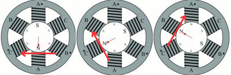
Figure 2. This image depicts the direction of force created by the changing of the magnetic field in the order of A, then C, then B. Image used courtesy of the author
Understanding the Phases
While the figure above depicts how the electrical forces work, we also have to understand that the coil sets must all be attached to a different phase. Just as the coils are spaced 120 degrees apart, we also have to space the timing of the peaks of our magnetic field by 120 degrees otherwise this would cause the rotor to bind and not rotate. So, to simulate this, we’ll use the sinusoidal field created by each phase as shown in Figure 3.
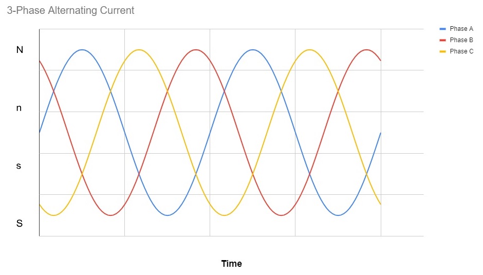
Figure 3. This image depicts the peak values of the current created for coils in the order of A, C, and B captured by a sine wave. Image used courtesy of the author
If we compare the previous figures, we can see that each coil and each line phase is shifted by 120 degrees, but what does that do for the stator and the motor?
With this shift in phases, the peak potential magnetic force shifts around the stator and creates that tangential force shown in Figure 2. In this example, we can see that our rotation would go from A (blue) to C (yellow) to B (red) or clockwise based on our figure.
So what if we wanted to go counterclockwise? As we already know, we simply swap two of the three leads. For example, in this scenario, we’ll swap the C and B leads. This would create the three-phase sine pattern seen in Figure 4.
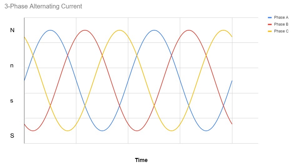
Figure 4. This image depicts the sine wave created if leads B and C are swapped, creating an order of A, B, C. Image used courtesy of the author
After reversing our B and C leads, we can now see that our peak magnetic fields are created in the order of A (blue) to B (red) to C (yellow), reversing the forces created from our initial setup, creating a counterclockwise rotation we can see in Figure 5.
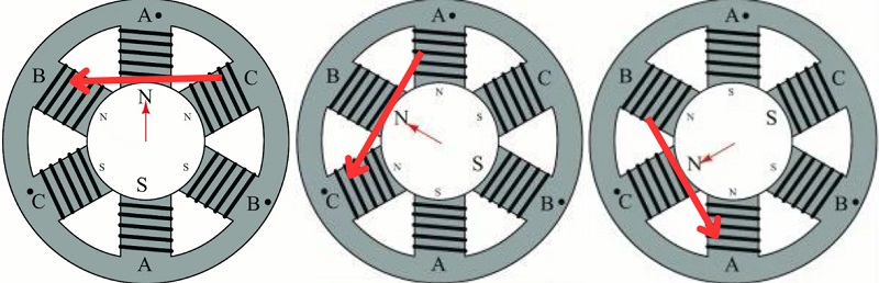
Figure 5. This figure depicts the reversal of the force created by the magnetic forces created when we swapped the leads: A, then B, then C. Image used courtesy of the author
Understanding the Wiring: Wye and Delta
For three-phase industrial motors, there are two types of winding designs, each presenting unique benefits. But do these differences affect the way in which the electrical fields are reversed when swapping leads?
Without going into too much detail about the differences (which constitute several articles in itself, like this one about motor wiring and this one explaining delta motors), I’m only going to focus on why these winding designs work to reverse the motor.
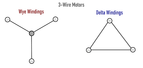
Figure 6. Wye (star or Y) and delta wiring. Image used ourtesy of Control Automation
In both the wye (Y or star) and delta coil arrangements, the resistive coils are split into three individual segments, as can be seen in Figure 6 above. This is the case regardless of the number of exposed T-leads in the motor, of which they may have 3, 6, 9, or 12. The three segments are equally distributed around the stator to provide balanced electrical force to the rotor.
The difference lies in the resistance between leads and, therefore, the amount of current leading to magnetic force. So, while the internal wiring arrangement may affect the horsepower of the motor, it does NOT influence the way in which we can swap leads to reverse the rotation direction.
Understanding Motor Wiring
Motor wiring isn’t a simple topic, as it requires an understanding of unseen electrical and magnetic forces. Even so, a basic knowledge of the operating principle behind a common practice can elevate your skills in preventing and troubleshooting costly motor problems.
Interested in more content about motors? We have plenty to choose from!
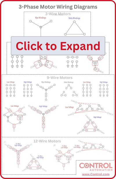
Handy Wiring Infographic:
eBook:
No-pressure Worksheet:
Articles:
- Comparing Single-Phase and Three-Phase Motors
- 3-phase Motor Types: Synchronous and Induction Motors
- Understanding Delta Wound Motors for Industrial Applications
- Brushed vs. Brushless DC Motors
- Field-oriented Control (Vector Control) for Brushless DC Motors
- Teardown: What’s Inside a 3-Phase Induction Motor?
Textbook: