Facebook
 Google
 GitHub
 Linkedin
Simulating Ladder Logic Programs in GX Simulator2 With Mitsubishi PLCs
GX Simulator2 is one of MELSOFT’s essential tools for the simulation of programs in a virtual PLC and works with GX Works2. Learn how to virtually simulate and test your ladder programs.
GX Works2 is a part of the Mitsubishi Electric software lineup powering the MELSOFT series of PLCs. This software has a valuable tool that can be used in place of the physical PLC hardware to simulate ladder logic programs. This can be very important both in the preparation and troubleshooting of existing systems, or in the case of training and learning when the physical hardware is not present.
The tool, known as GX Simulator2, is a powerful tool that functions seamlessly with a perfect visual representation for the feel of functionality. In this tutorial, we are going to write a simple ladder program and virtually execute it using the simulator tool.
Getting Started with a Simple Program
To get started, we need to have the GX Works2 software installed on our PC.
Once that's done, launch and create a new project. Begin by writing a simple ladder program with a normally open contact and a standard momentary output coil command, using addresses X000 and Y000, respectively, then compile the written ladder to be sure it's designed properly.
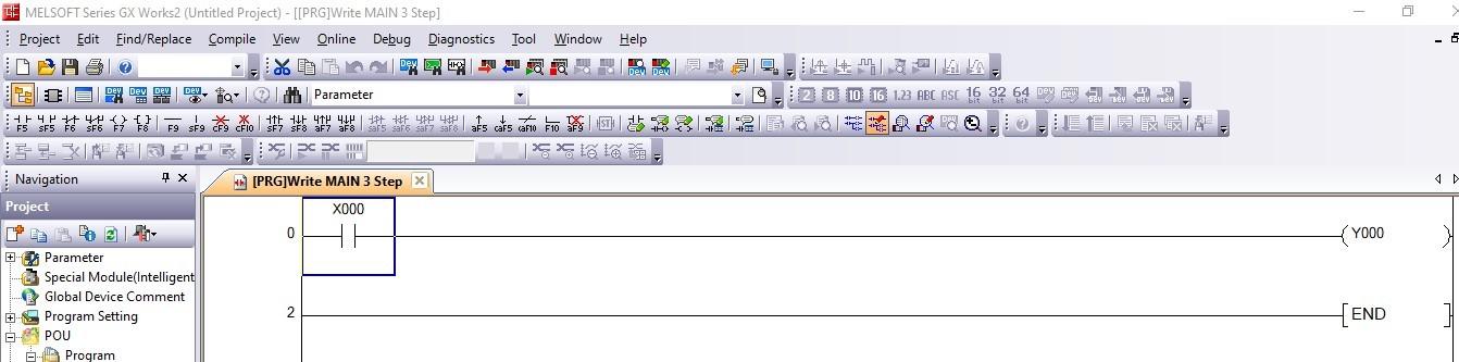
Figure 1. Simple ladder program to be simulated.
Activating GX Simulator2
With our written program ready, we can click the simulator icon in the top toolbar, which is shown in Figure 2 below. This will activate the simulator and a pop-up window will appear showing the conditions of the virtual PLC, whether in RUN or STOP mode.
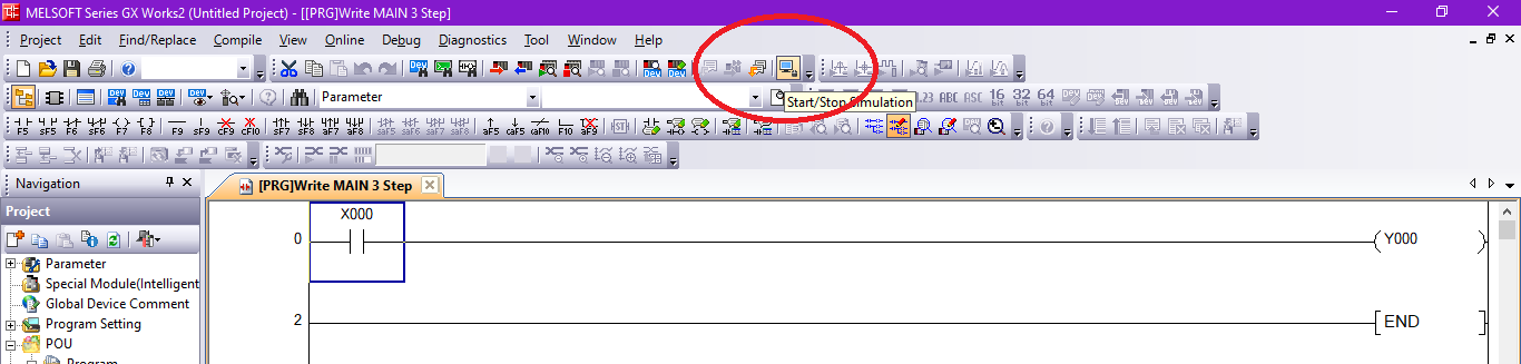
Figure 2. Start or Stop the Simulation by clicking on the blue icon.
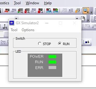
Figure 3. GX Simulator2 shows the status of the virtual PLC.
Writing a Program to GX Simulator2
The process of loading a program to GX Simulator2 is similar to loading it in physical PLC hardware; however, the simulator does not need any connection setup. Before writing the program, we need to ensure that the GX Simulator2 window is set to STOP mode. To write, we click on ‘online’ in the top ribbon, then ‘Write to PLC’. A window will appear where we can select all program, parameter, and comment data, then click on ‘Execute’.
Note that the communication channel is set to ‘Simulation’ at the top.
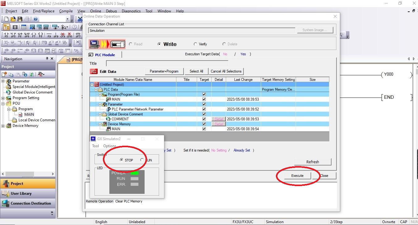
Figure 4. Writing a program to GX Simulator2.
After the execution is complete, we can close the window and try simulating the loaded program by switching the simulator back to RUN mode and starting the device test.
Device Test
A device test is where an input contact is turned on or off to view the output status of the ladder program. Before starting the device test, we need to first ensure that the simulator is activated and ‘Monitor’ mode is selected to allow for the visualization of the status of both the input contact and the output coil. To test the behavior of the program, we click on the Modify Value icon shown in Figure 5 below, located in the toolbar of GX Works2 software. The icon is used to modify the value of an input or output.
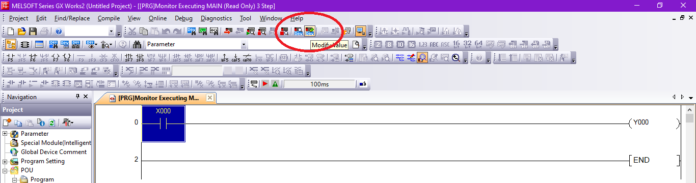
Figure 5. ‘Modify Value’ button for device test operation.
Once Modify Value is clicked, a pop-up window appears in which a device or label is input and either turned on or off. The window also allows for the change of data types via a drop-down menu. Such data type choices include bit, word, double word, and string. To simulate the condition of the normally open contact from our written ladder program, we click on ‘ON’ from the window.
In the simple ladder logic, the contacts are highlighted in blue to indicate the energized state, and not highlighted otherwise. In this case, when the N.O. contact is on, there is a blue highlight in both the contact and the output coil.
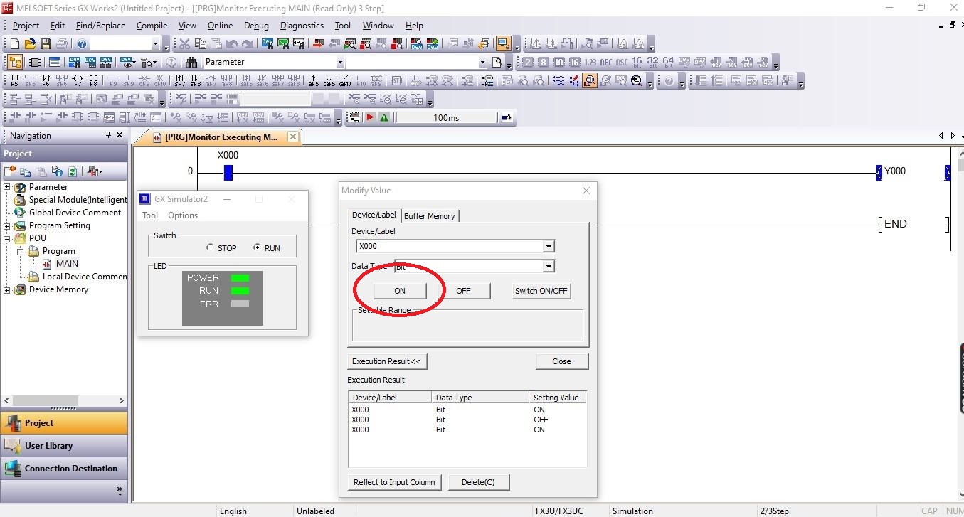
Figure 6. N.O. X000 turned ON from the modify value window, highlighting the contacts to simulate their status.
When OFF is clicked from the device test window, the blue highlight disappears from both the input contact and the output coil. We can therefore conclude from the output of this simulation that the N.O. contact X000 has to be on to power the output coil Y000, which is a fairly standard, simple illustration of ladder logic.
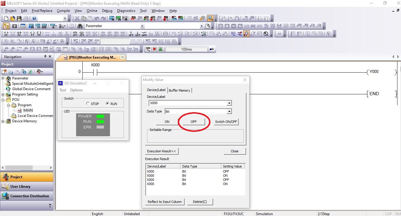
Figure 7. N.O. X000 turned OFF from the modify value window, removing the highlights from the contacts to simulate their status.
Testing a Virtual PLC in GX Simulator2
GX Simulator2 is an essential tool to test and debug ladder logic programs. Understanding how to work with the tool is simple, even if you are an absolute beginner, however, you need to at least have some basics of how to use GX Works2 programming software. Follow this guide to understand how to test and simulate your ladder programs.
Happy programming!
Need more information about getting started with MELSEC PLCs?
Introduction to Mitsubishi PLC - FX Series and MELSOFT GX Developer
Using Set/Reset Instructions in Mitsubishi’s MELSEC PLCs
Want to test your ladder logic programming skills?
Check out Control Automation’s PLC programming worksheet