 Facebook
 Google
 GitHub
 Linkedin
Orifice Plate Sizing for Flow Measurements
Learn about orifice plates and specifically how to size orifice plates for flow measurements and the different flow rates associated with them.
One of the most common methods for measuring a fluid's flow rate in a pipe is to create a change in the fluid's velocity, which will cause a pressure drop. If the pressure drop can be measured, the velocity can be determined and the flow rate. Orifice plates are a very common source of pressure drop, but choosing the plate's right type and size is essential.
Sizing an Orifice Plate for Flow Measurements
Any system that deals with the transportation of fluids must be very aware of the rate at which the fluid is traveling. This measurement is either a volume flow rate with units like meters^3 per second or gallons per minute. Alternatively, the rate may instead use the fluid's density to return a mass flow rate in kg per second.
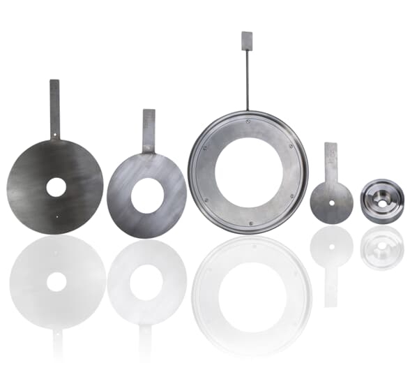
Various orifice plates. Image courtesy of ABB.
A fluid can either be a gas or liquid, and similar measurement methods may determine the flow rate. In many cases, this method is by creating a drop in pressure as the fluid flows downstream. If the fluid velocity can increase, the pressure will drop through fluid dynamics that explain the Bernoulli Principle and be responsible for a lift on an airplane wing.
One can increase velocity by restricting the flow diameter suddenly, which is the purpose of an orifice plate. The plate mostly includes a central (concentric) hole bored into a steel plate installed between two flanges in a pipe section. A pressure sensor placed upstream and another downstream, providing an accurate pressure drop measurement. This pressure drop determines the velocity of the fluid, which, when multiplied by the plate bore opening area, yields the flow rate.
A couple of different designs for plates include offset bores ('eccentric') where the bore is not in the center. There are also different downstream countersinks and counterbores used to achieve the right flow conditions. For this article, we will consider the standard concentric bore.
Choosing the plate's appropriate size and bore opening is often accomplished by software and an engineering team. Still, it involves several factors, including the size of bore versus the pipe diameter, the min and max flow rates, and the strategy for measuring the drop in pressure from upstream to downstream.
Pipe and Orifice Diameter Ratio
There is a term to simplify the mathematical relationship between pipe and orifice bore - "Beta." This is the bore size diameter of the orifice plate, called (d), divided by the inner diameter of the pipe (D). This leads to the equation:
$$ \beta=d/D $$
Since the bore opening is always smaller than the pipe, this ratio will always be less than 1.
Extreme Beta values can lead to two problems - a value close to 1 means a large bore opening. This will cause less of a velocity change, and therefore less pressure change. The measurement will be less accurate. A small-bore means a small Beta value, and an extreme restriction in the pipe causes a large disruption to flow.
This idea illustrates two critical concerns with orifice plates. These problems should always be considered, although they don't have to be so bad that they prohibit the implementation of the plate method.
The pressure drop from the orifice plate reduces the available pressure for the rest of the downstream system. The source (pump, compressor, etc.) must be able to provide the required pressure + the drop associated with the pipe length and valves + this new pressure drop from the orifice plate.
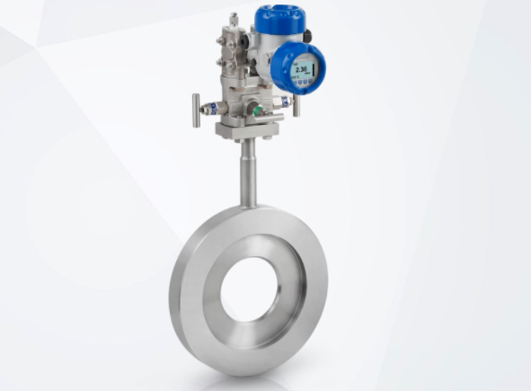
DP flowmeter for volume flow measurement of liquids, gases, and steam with an orifice plate. Image courtesy of the KROHNE Group.
The orifice bore must still allow enough flow rate to supply the system properly. This is a factor of consideration in the design. A smaller opening may increase the velocity, but it is not linear due to friction and flow dynamics. Too small of a bore may result in too little flow for the proper operation of the system.
A common recommendation for the proper Beta value is between 0.3 and 0.7. This means the bore diameter is between 30% and 70% of the pipe ID.
Min and Max Flow Rates
Flow rates change from time to time in a system. This change is the reason for measuring the flow in the first place. When sizing the bore diameter, the maximum possible flow rate must be known so that the bore can allow such flow. If the flow is any less, then it will be able to pass through.
The caution is that the accuracy of the measurement decreases as the flow rate decreases. This is because the velocity will also decrease, leading to a smaller difference in up/downstream pressures.
If the maximum flow is too large, the average flow you would expect to see is lower and less accurate. Be sure to accommodate the true maximum flow rate but do not select too excessive of a maximum value, or you can expect to see less accuracy over time.
Pressure Drop
In many ways, this design criteria mimics the Beta value since the bore opening affects the drop in pressure from one side to the other.
Considering just the drop in pressure, the lowest possible pressure drop is 0 (units may be psi, Bar, Pa, etc.). The largest pressure drop indicates the range of scale you should use. The larger the maximum pressure drop, the more accurate the measurement. The likely desire would be to have the most precise measurement possible. The risk of such a decision is that a large pressure drop will reduce the system's remainder pressure. This was the same statement made in point #1 earlier in the article.
Changing the Beta value changes the expected pressure drop, so the two factors are related. However, the proper orifice plate design must achieve both the proper pressure drop range for accurate measurements, but it must also not restrict the pressure.


The definition of Beta in this article is incorrect. Beta is the ratio of the orifice plate bore diameter, d, to the inside diameter of the pipe, D. Hence Beta = d/D.