Facebook
 Google
 GitHub
 Linkedin
Stepper Motor Control for Mitsubishi’s FX Series PLCs
Stepper motor control can be useful for motion applications. Learn the circuit connection and programming instructions for implementing stepper motor control using GX Works 2 on MELSEC FX-Series PLCs.
Stepper motors are high-precision motors that move in small, incremental steps with a high degree of accuracy. These types of motors are used in precise control automation applications such as CNC axes, conveyor belts, and mobile platforms. In this tutorial, we are going to look at the PLC control program instructions for stepper motor control in Mitsubishi’s FX series of PLCs.
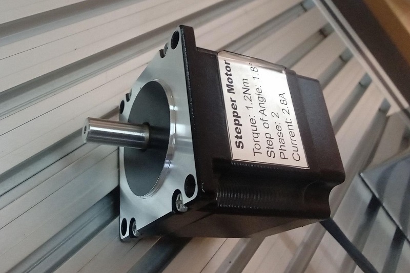
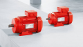
Figure 1. Typical stepper motor rated for 1.8 degrees per full step. Image used courtesy of the author.
Hardware Requirements for Stepper Motor Control
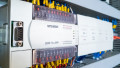
To implement the control of a stepper motor, there are a couple of hardware requirements. This hardware includes; the stepper motor to be controlled, the FX series PLC, SC09 programming cable, CW230 stepper motor drive, and a programming PC with GX Developer or GX Works 2 software installed.
Never try to drive a motor directly from PLC output terminals, always use a motor driver board. The current required from the coils (2.8 amps in the motor in Figure 1) would likely destroy the PLC outputs.
Wiring Connection
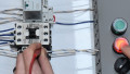
Most basic bipolar stepper motors have four wires that are used to switch the coils of the motor in phases to achieve precise step control. The motor, therefore, needs a driver device to constantly switch the polarity of its coils in specific frequencies. This is where the CW230 motor drive board and the FX series PLC step in.
In the connection diagram below, the 4 wires of the stepper motor coil are connected to the motor drive, and the CP (Pulse, P) connection of the drive is connected to PLC input terminal Y000 where the pulse will be generated. To define the direction of the motor, the contact CW (Direction, D) of the drive is connected to PLC output terminal Y002.
In the below diagram, this PLC is wired for sinking outputs, which means that the PLC output common terminal is connected to 0 V. If the PLC outputs are sourcing, connect Y0 and Y2 to P+ and D+, respectively, and connect P- and D- to 0V.
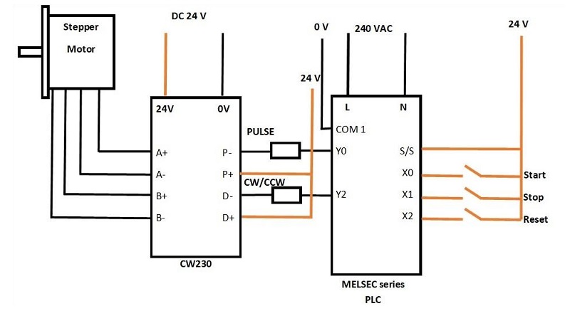
Figure 2. Wiring connection of stepper motor to the PLC. Image used courtesy of the author.
Configuring the Stepper Motor Parameters
Before turning to PLC programming, there are a couple of configurations that should be considered. While using the CW230 motor drive, the current and the micro-step should be set according to the control needs. The motor drive has tiny white DIP switches that are set as either high or low (1 or 0).
| M1 | 1 | 0 | 1 | 0 | 1 | 0 | 1 | 0 |
| M2 | 1 | 1 | 0 | 0 | 1 | 1 | 0 | 0 |
| M3 | 1 | 1 | 1 | 1 | 0 | 0 | 0 | 0 |
| Microstep | 1 | 1/2 | 1/4 | 1/8 | 1/16 | 1/32 | 1/64 | – |
Table 1. Micro step choices dip switch settings for CW230 motor drive.
| M5 | 0 | 0 | 0 | 0 | 1 | 1 | 1 | 1 |
| M6 | 0 | 0 | 1 | 1 | 0 | 0 | 1 | 1 |
| M7 | 0 | 1 | 0 | 1 | 0 | 1 | 0 | 1 |
| Current (A) | 0.9 | 1.2 | 1.5 | 1.8 | 2.1 | 2.4 | 2.7 | 3.0 |
Table 2. Current stepper motor drive dip switch settings for CW230 motor drive.
Writing the Control Program
To better understand the control program, we need to understand the breakdown of the program syntax in Mitsubishi’s MELSOFT series GX Works2 or GX developer. The syntax of the ladder command appears as follows:
–[PLSY S1 S2 D]-
or
–[DPLSY S1 S2 D]-
The first option, PLSY, is used in 16-bit applications while DPLSY is used in 32-bit (yielding an often higher maximum frequency and step count) to generate pulse trains in a single direction.
S1 represents the output pulse frequency (steps per second) and is denoted as a K followed by the variable number, for example, K100.
S2 represents the number of output pulses and is also denoted with K followed by the pulse variable.
D represents the output address of the step input to the motor drive. Note: you cannot use the slower relay outputs for stepper motor driving, only transistor outputs capable of the high switching frequency demands.
Using the 16-bit PLSY syntax, we can load the program below to the PLC where the output pulse frequency is 500 and 300 is the number of output pulses. X000 and X001 are the start and stop push buttons, respectively. M0 represents an internal memory coil of the PLC while Y000 is the actual pulse output address.
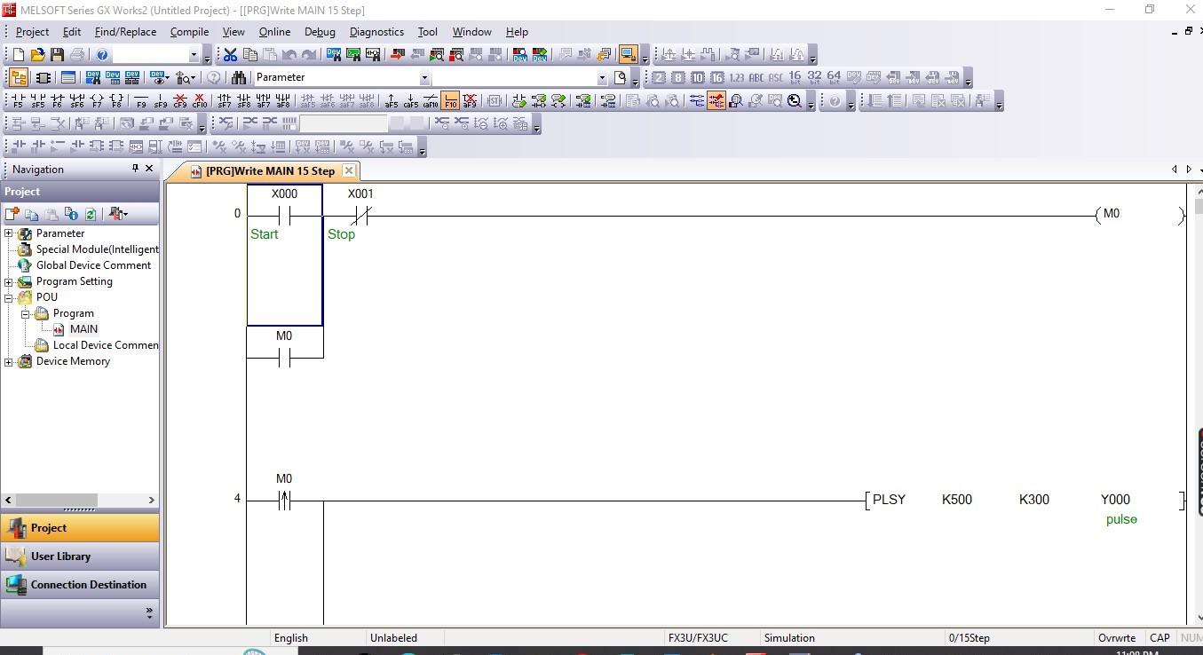
Figure 3. Stepper motor control using PLSY instruction is used to generate a continuous pulse train.
The 32-bit DPLSY instruction can be used in a similar fashion, but depending on the FX CPU in use, the frequency can be higher and the pulse count can be higher.
Advanced Stepper Motor Control Instructions
Stepper motor control instructions depend on the need for rotation you intend to achieve. In this case, aspects like rotation speed, direction, number of steps, and continuous rotation are considered. Therefore, there are special instructions to achieve this. Below are some advanced stepper motor control instructions that can be implemented in MELSEC series PLC using GX Works 2 and GX Developer;
DRVI Instruction
DRVI is a positioning instruction that is used to provide relative (incremental) instructions to the drive mode in position control. The syntax for the instruction is given by –[DRVI S1 S2 D1 D2]- Where S1 and S2 represent the output pulse frequencies and the number of output pulses relative to the current position, respectively. D1 and D2 are data devices representing the pulse output and the direction output. The pulse output can be a positive or negative value, while the direction output can only be a positive value, either 16 or 32 bits. DRVI is used for 16-bit while DDRVI is used for the 32-bit.
To better understand this, consider the ladder logic diagram below, which shows the instruction in use for both forward and reverse. For reverse rotation, a negative sign is placed before the output frequency value.
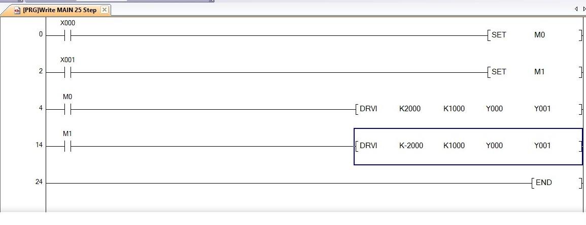
Figure 4. DRVI relative positioning instruction ladder example for both forward and reverse.
DRVA Instruction
Similar to DRVI, which sends incremental instructions relative to the motor’s current position, the DRVA instruction provides a command to an absolute position. This requires an ability to reset of ‘home’ the origin address so that all future commands can track the position with respect to that origin point.
ZRN Instruction
This is a zero-return instruction used in positioning control. This command sends the motor to an absolute zero point, first at a high speed indicated by S1, until a close proximity switch limit is reach at input D1. At that point, a lower speed determined by S1 will take over until the zero location is reached.
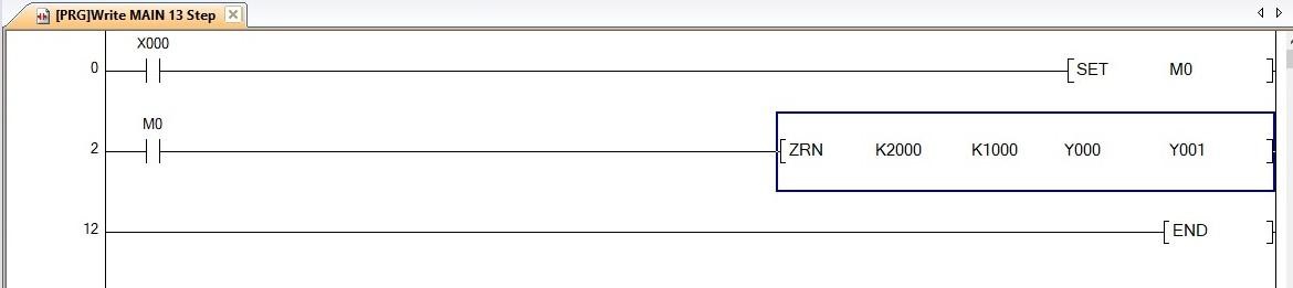
Figure 5. Zero return instruction (ZRN) ladder example.
There are a variety of other useful positioning instructions, including dog search zero return (DSZR), variable speed pulse output (PLSV), drive to absolute (DRVA), Interrupt positioning (DVIT), batch data positioning mode ([D]TBL), and acceleration/deceleration setup pulse Y output (PLSR).
Stepper Motor Control
With the immense applications of stepper motors in the field of control and automation, an engineer or a control automation enthusiast needs to grasp the knowledge of implementing precise control of these motors. Follow this guide to heighten your understanding of programming stepper motors in Mitsubishi’s FX series PLCs. As always, the best way to learn about industrial automation and control is to jump in and get started.
Happy programming!
If you want to get started with ladder logic programming, check out Control Automation’s PLC programming worksheet.
Featured image used courtesy of Adobe Stock
Related Content