Facebook
 Google
 GitHub
 Linkedin
Tutorial | First Program Using Rockwell’s Micro800 Series PLC
Rockwell Automation’s Micro800 series is the modern replacement for some older MicroLogix PLCs. Learn how to get started with basic I/O, plus timers and counters, to build your own programs in a snap!
The Micro800 series of PLCs is one of the smallest PLCs currently manufactured by Allen-Bradley as a part of Rockwell Automation. This basic platform begins with a modest set of discrete I/O points embedded along with the CPU. Most models support add-on modules to provide a wide array of analog and communication options. This lineup of PLCs is also supported with Rockwell PowerFlex and Kinetix motor drives and PanelView graphic terminal compatibility through the free Connected Components Workbench (CCW) software. All in all, a great little device for designing state-of-the-art machine centers where the design requirements do not necessitate a large, modular system.
Connecting I/O Devices to the Micro800
This guide is a walkthrough of general procedures, but be sure to review your specific model number’s user guide. The Micro800 series of PLCs has many varieties with relay, source, and sink I/O. Connecting the wrong wires to any PLC can be dangerous. If you are unfamiliar with wiring, have a look at our handy tutorial videos for a walkthrough of I/O for PLCs.
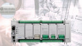
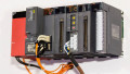
For this setup, I am using a Micro830 with 28 discrete inputs and 20 sourcing outputs.
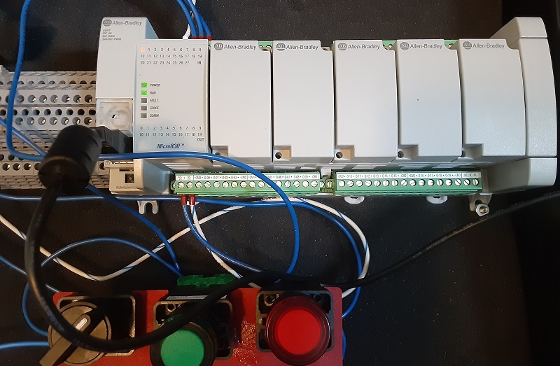
Figure 1. The Micro830 PLC trainer in a small case with a few I/O devices.
I connected the COM0 (the common on the input side) to the 0 V side of my DC power supply. Since this is a DC output PLC, I connected the +CM0/-CM0 (the commons on the output side) to the +24 and 0 V sides of my DC power supply, respectively.
I have connected a NC pushbutton to terminal I-00, a NO pushbutton to terminal I-01, and a quarter-turn switch to terminal I-02.
Connected Components Workbench (CCW)
I am using the most recent version of CCW, which is version 21.01. To my enjoyment, there were many similarities between this software and so many others that I have come to enjoy, including others created by Rockwell Automation. If you know your way around a PLC even a little bit, you should have no problem following this guide.
Begin as you might expect, by starting a new project, as shown in Figure 1. At the bottom of that box, there is a check applied to ‘Add Device on Create’ which is a simple method if you know what PLC you will be programming.
Alternatively, you can un-check that box and ‘Discover Device’ to upload from an existing workstation. If adding a new device, you just need to select the right CPU model number.
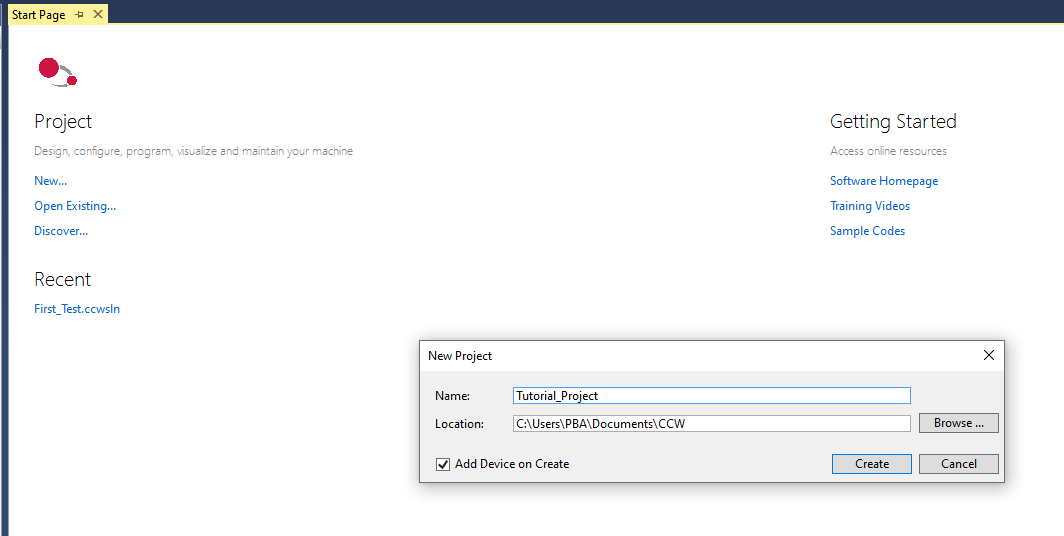
Figure 2. New project creation
For those engineers familiar with the common Controller Tags and Program Tags, the name you will find in CCW is variables, both global and local variables.
Upon device creation, a few system tags are added to the global variables as well as all of the built-in I/O addresses, so you don’t need to create them manually. However, you can immediately navigate to the Global Variable listing and add aliases for those buttons we installed. The names for built-in I/O will not follow the standard addresses used in Studio 5000, so adding aliases might be helpful.
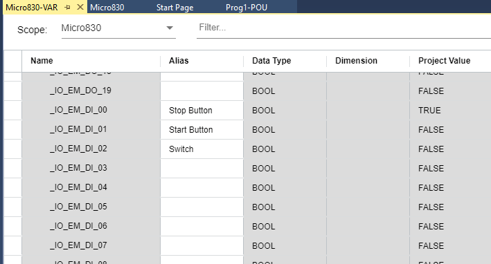
Figure 3. Aliases can be defined easily for each global I/O address.
Now over to the actual ladder logic programming. While still disconnected from the PLC (you can’t make program edits online currently in CCW), right-click on the ‘Programs’ section of the left sidebar to add a new ladder diagram.
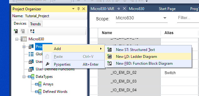
Figure 4. Adding a new Ladder Diagram (LD) program to a project.
Editing Ladder Diagrams in CCW
In the ladder editor, the ‘Favorites’ tab is loaded with the most commonly used commands. If you find yourself in constant use of other ones, right-click them and ‘Add to Favorites’.
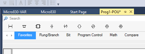
Figure 5. You can easily edit the ‘favorite’ instructions list.
All the familiar commands are here: XIC and XIO, as well as outputs and some branching commands.
It’s worth noting right here that there are several keystrokes that can greatly simplify the programming. For example, say you have a set of instructions that need to be surrounded by a parallel branch of the rung. Select both of those instructions, right-click, and insert a new ‘Surround With Branch’ so you don’t need to drag the branch around the rung. You can also simply hit Ctrl+7, if you happen to remember that hotkey.
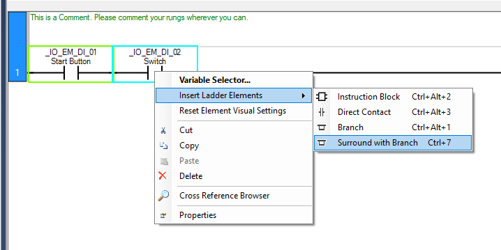
Figure 6. A few hotkeys can make programming a lot faster.
When sufficient input contacts and output coil(s) are added to your program, download it to the PLC by clicking the download button at the top. The PLC will connect, go online, and make sure it’s switched to RUN mode to execute the program.
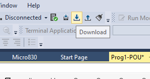
Figure 7. Downloading the new program
Timers and Counters in CCW
For veterans of Rockwell products, the timers have a bit of a curve ball. But to be honest, this aligns CCW with typical IEC formats, where most languages already use terms like IN, Q, PT, ET, etc.
First, head over to your Local Variables menu, disconnect from the PLC, and make a new timer tag. Call it ‘Sample_Timer’ and select the TON data type. The difference between creating a TON and a TOF is that an off-delay timer uses the falling edge of the input signal to trigger the timer start, so you will find an ‘FEdge’ tag inside. The TON uses a rising edge, so it contains an ‘REdge’ tag.
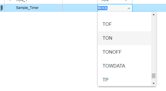
Figure 8. Adding a new TON (timer) variable
With our new timer variable created, head back to the ladder program and drag a TON into a new rung. It will try and create a new TON_1 variable, but double-click and start typing ‘Sam…’ into the Instance at the bottom. It will autofill with the new Sample_Timer.
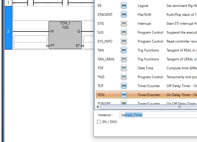
Figure 9. When a new timer is created, provide it with a name from the variable list.
We need a trigger for the input, I’ll use my selector switch.
We also need an output on the Q line, I’ll use one of the output terminals, which I have aliased as Start Contact.
The ET (elapsed time) tag already exists, so we do not need to insert anything into that box. But we do need to define a PT, preset time.
Most languages default to a time base, like milliseconds or 1/100 of a second. In CCW, you can type whatever ms, sec, min, hrs you like, you just need to write it properly. For this tutorial, I’ll make a 1 min 30 second timer. You could say 90 seconds, but you can mix it up too!
Begin any ‘Time’ data type with T# followed by the time amount: T#1m30s in this case. To measure time in hours or milliseconds, use h or ms just like this.
Download the program, be sure to switch to RUN mode, and energize the switch.
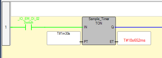
Figure 10. The running timer program.
After 1-½ agonizingly long minutes, the Q output energizes, and the Start Contact with it.
To program counters, a very similar approach is used, with CU as the input, Q as the output, and PV and CV indicating the preset count value and current count value. The preset is simply a quantity this time, and needs no time units.
To apply a counter, you also need to provide a Reset input. In this example, I have used a ‘Sample_Counter’ variable with a preset of 100. The start button will reset the counter.
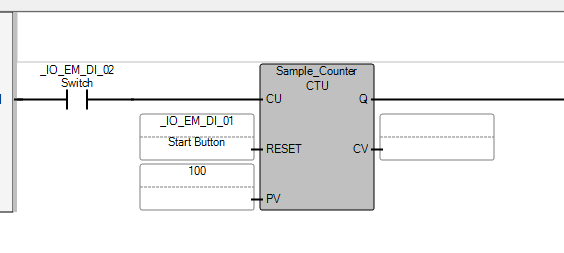
Figure 11. A sample counter function.
Formatting Colors
To keep consistent with many of my familiar PLC IDEs, I wanted to set the color of the energized instructions to be green, rather than the default red color.
Navigate to Tools -> Options and the ladder diagram section allows you to customize the colors for each element and action. ‘Power Flow True Color’ is the item of interest here, which I have set to Lime.
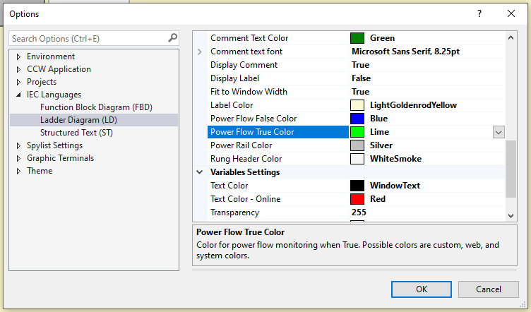
Figure 12. Customizing the colors used in the ladder editor.
Programming PLCs
The best way to learn PLC programming is to get out and DO IT.
Interested in learning about other PLC types? We have plenty of tutorials!
Rockwell Studio 5000 and CompactLogix PLCs
Siemens TIA Portal and S7-1200 PLCs
Automation Direct Productivity PLCs
Arduino PLC IDE and Opta / PMC Platform
Mitsubishi GX Works and MELSEC PLCs