Facebook
 Google
 GitHub
 Linkedin
Understanding Hairpin Stators in High-Efficiency Motors
Hairpin motors are becoming popular with electric vehicle manufacturers, but what sets them apart from traditional electric motors? And, if they are so great, why not use them in all applications?
Electric motors use magnetic force to convert electricity into rotary motion. There are many different kinds of motors and they all have unique benefits that suit them well for certain applications. However, one particular motor design has recently become popular with the electric vehicle industry: the hairpin stator electric motor.
Turning Electricity Into Rotary Motion
A hairpin motor is a type of induction AC motor, and as with all induction motors, the stator is not a permanent magnet, instead using copper wires wrapped around iron cores to form electromagnetic rotational force when electricity is passed through the wires.
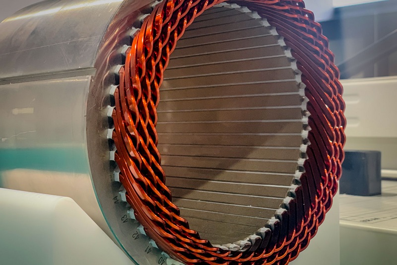
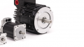
Figure 1. Hairpin stator motors share a similar shape as traditional induction windings, but with higher power density. Image used courtesy of BBS Automation
What sets the hairpin motor apart from other electric motors is how the copper windings are arranged around the stator to increase operational efficiency.
The Core Of The Electric Motor
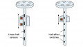
Electric motors consist of two main pieces: the rotational component called the rotor, which is usually the center of the motor, and the immobile stator around the outside. In an induction motor, the stator is designed with many long iron cores with bundles of stranded copper wire wrapped around, all parallel along the longitudinal axis.
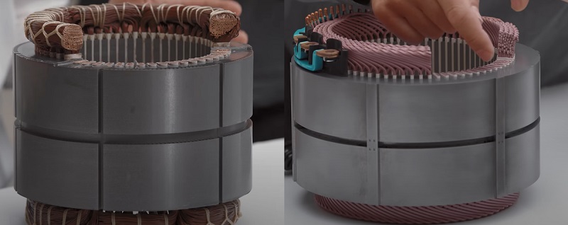
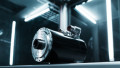
Figure 2. The contrast of stranded wire bundles to the solid cross-section of the copper hairpins. Image used courtesy of Lucid Motors
When an electrical current is passed through the different sets of wire bundles, that section of the stator will generate a strong magnetic force. This force pushes (and pulls, as all magnets have opposing polarities) against the rotor, creating the spinning motion.
Inside a hairpin stator, there are still copper wires wrapped around iron cores, only instead of stranded wires, solid copper rectangular wires, almost like bars, are bent into a shape similar to a hairpin and then inserted into the stator core. With a traditional stator, all the strands of wire need to be bundled and laboriously stitched together, a process known as stator lacing. With a hairpin stator, the bundles are twisted and welded, so no lacing is required.
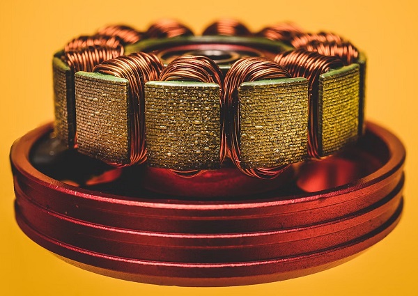
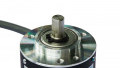
Figure 3. Traditional strands of wires ‘wrapped’ around each iron core. Image used courtesy of Unsplash
Production Of The Stator
With the copper hairpins being vastly different from a bundle of wires, there is a different production process required to manufacture a hairpin stator.
The copper wire is received from a supplier in bundles that need to be unwound and the wire straightened. Next, the wire is formed into the signature ‘hairpin’ shape with the use of servo motor bending machines. The shape of this wire must be very accurate because of the tight tolerances of the slots into which the wires are inserted.
Once the wires are formed, some of the insulation needs to be removed from both ends to make proper electrical connections. There are two methods for this process, one being lasers and the other a mechanical process using brushes. Laser insulation removal is the most efficient and requires less maintenance.
Once the ends are clean, the wires can be inserted into the stator and then twisted to form that iconic shape. The insertion machine also needs to be precise with its positioning so that the wires do not clip the side of the slots in the stator.
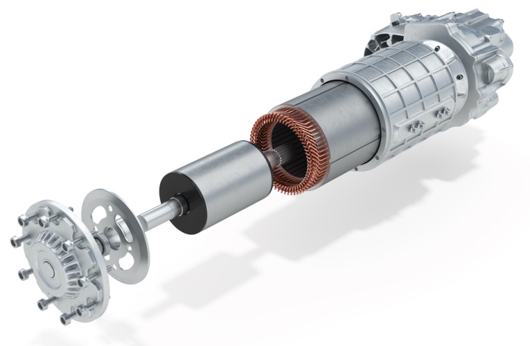
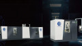
Figure 4. From a distance, the stator of a hairpin motor is quite similar to bundled windings. Image used courtesy of Zeiss
Why All The Fuss with Hairpin Motors?
Efficiency is today’s driving factor for most of the changes that happen to well-established devices within the industry, and the electric motor is no different. To get an electric motor to be more efficient, one method is to maximize the amount of magnetic force in the stator. With a traditional motor, the copper wires are round, so when they are all bundled together, small air gaps are left between some of the wires. These gaps result in less magnetic force per size of the stator. With the hairpin configuration, the rectangular wires can fit tightly together with no air gaps, thus maximizing the amount of magnetic force allowed in the motor. A larger magnetic force per volume means manufacturers can make the overall motor smaller and lighter.
With the hairpin windings being thicker, more symmetrical, and more accurately formed, there is less energy loss through the windings and a smaller chance of failure. This reduction in energy loss results in better performance at both low-speed and high-speed torque.
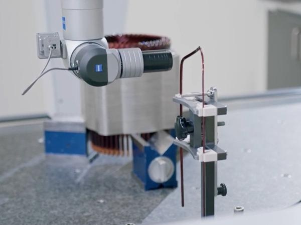
Figure 5. Due to the tight positional tolerances, each ‘hairpin’ must be carefully twisted and then inspected before assembly. Image used courtesy of Zeiss
Should All Induction Motors Use Hairpin Stators?
If they are so much more efficient, why shouldn’t all electric motors employ this design? That would be nice, but unfortunately, the production of these stators requires some advanced equipment and this doesn’t come cheap.
The forming of the wires needs to be very accurate and repeatable so that the wires can be inserted into the stator without issues. The twisting, stripping, and welding are all performed using precision servos and lasers. Most, if not all, of these processes can only be done with equipment that requires a heavy monetary investment from the manufacturer. Traditional windings can mostly be done manually, making the manufacturing process cheaper in places with a lower labor cost.
For applications where every ounce of weight matters and efficient use of energy is crucial, such as electric vehicles, the added investment can be justified and the costs are acceptable to the consumer. However, when your application requires a more simple constant spinning of a cooling fan or moving a conveyor at a specific speed, the traditional low-cost induction motor might be the better choice.