 Facebook
 Google
 GitHub
 Linkedin
Using Structured Text in OpenPLC | Warning Simulator Tutorial
With a C++ extension, monitoring of status and warning messages can easily be displayed with OpenPLC. Arduino PLC variables can then be observed using a serial terminal or monitor.
OpenPLC provides a software platform that converts any microcontroller into a small PLC. The IEC 61131-3 standard allows this PLC to be programmed using five languages:
- Instruction Lists (IL)
- Structured Text (ST)
- Sequence Function Charts (SFC)
- Function Block Diagrams (FBD)
- The traditional Ladder Diagram (LD)
One previously unexplored feature of OpenPLC is the ability to send messages to a serial terminal or monitor. With the use of an extension, we can provide a warning or debug status of the controller.
This project article explores this Arduino extension feature by building a simple warning message simulator using OpenPLC on an Arduino Uno.
What is an Arduino Extension?
This extension is a small snippet of C++ code that extends the IEC 61131-3 standard by using the programming language structure associated with the Arduino ecosystem, which uses the familiar functions of void setup () and void loop ().
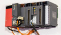
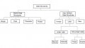
Figure 1 illustrates an example of an embedded controller project followed by Figure 2 showing a partial programming structure for this arrangment.
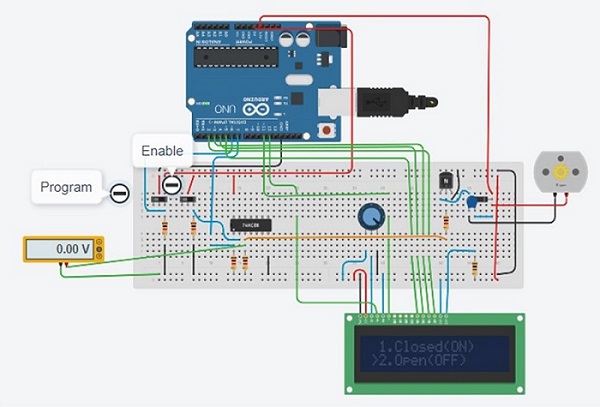
Figure 1. A programmable DC motor controller.
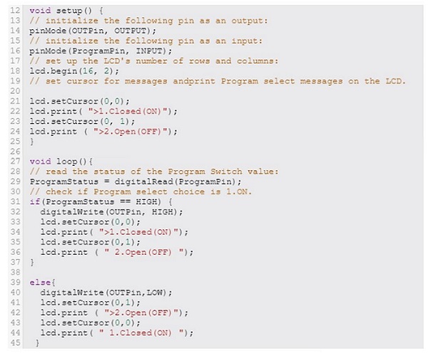
Figure 2. A snippet of code for an example DC motor controller.
The OpenPLC editor contains example projects that illustrate the use and structure of extensions. The LD that will be modified for the warning message project is the Arduino_Serial_Print example, shown in Figure 3 below.
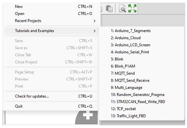
Figure 3. The list of examples included with the Arduino extension.
The Serial Print example allows messages from the OpenPLC LD to be sent and received by a serial terminal (monitor), like the one natively included in the Arduino IDE.
By modifying the extension, any system, status, or debug messages from the Arduino PLC can be viewed on a serial terminal. Figure 4 shows the C++ code for the Arduino_Serial_Print example.
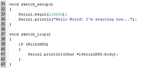
Figure 4. An Arduino extension example using Serial.println.
The Serial.begin(115200) instruction shown at line 33 establishes the baud rate for receiving the warning message from the LD.
Line 34 uses Serial.println to provide an introduction header for the received message.
The conditional instruction of if (PrintMsg) at line 39 checks for a warning message sent by the LD.
The warning message will be sent to the serial terminal by the Serial.println((char*)SerialMSG.body) instruction of line 41.
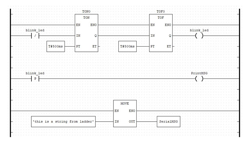
Figure 5. Arduino 'Serial Print' LD.
Figure 5 shows the complete ladder diagram to accompany the extension code. Using the TON0 and TOF0 timer function blocks, an external LED will blink ON and OFF every 500ms for a total switching time of 1 sec.
The SerialMSG ‘this is a string from ladder’ is sent to the serial terminal every time the LED turns on (positive-going edge).
The MOVE instruction allows the user to place any text string into ‘SerialMSG’ as the outgoing message.
The Warning Message Simulator
Our message simulator demonstrates how text can be sent from an LD to a serial terminal. The concept of the simulator’s operation primarily detects the actuation of a pushbutton, then transmits the message and also energizes an LED.
The pushbutton contacts have a 20ms actuation time, providing debouncing for the switching component. The LED will blink within the 20 ms actuation time. With each pushbutton actuation, a warning message is sent to a serial monitor or terminal every 20 ms. The displayed warning message and LED are consistent with the press and release action of the PB switch.
Figure 6 illustrates a block diagram of this simulator process.
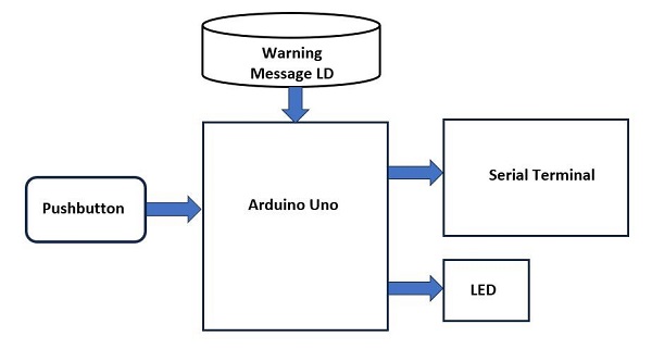
Figure 6. The Warning Message Simulator Concept Diagram.
Warning Message Simulator: Hardware
As seen in Figure 6, the warning message simulator requires wiring a few off-the-shelf electronic components to an Arduino. The project is built following the wiring diagram in Figure 7, which comes from one of our very first OpenPLC project articles.
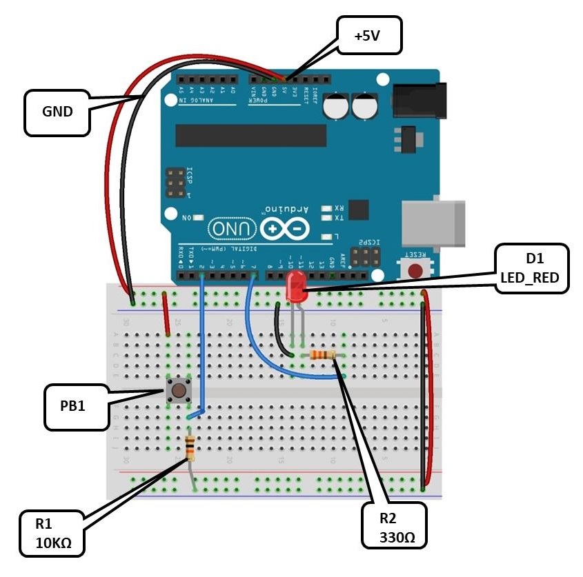
Figure 7. The simulator wiring diagram.
The physical layout and wiring of the electronic components are shown on a solderless breadboard in Figure 8.
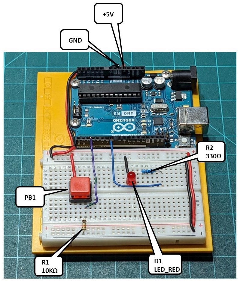
Figure 8. The Arduino PLC breadboard.
As a final reference, the circuit schematic diagram for the warning message simulator is shown in Figure 9.
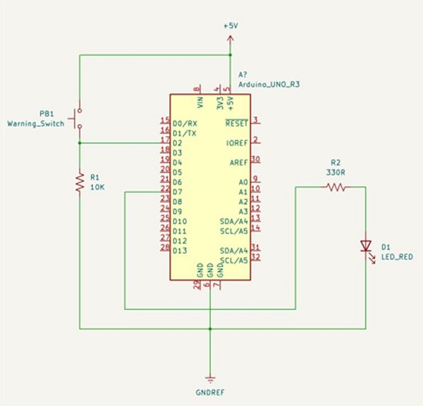
Figure 9. The warning message simulator schematic diagram.
Warning Message Simulator: Software
Now that the hardware for the simulator is built, the next step is constructing the software of both components: the LD and the Arduino extension.
The I/O tag listing and the LD is shown in Figure 10. The tag listing and LD are built using the instructions presented in the Arduino OpenPLC introduction project article.
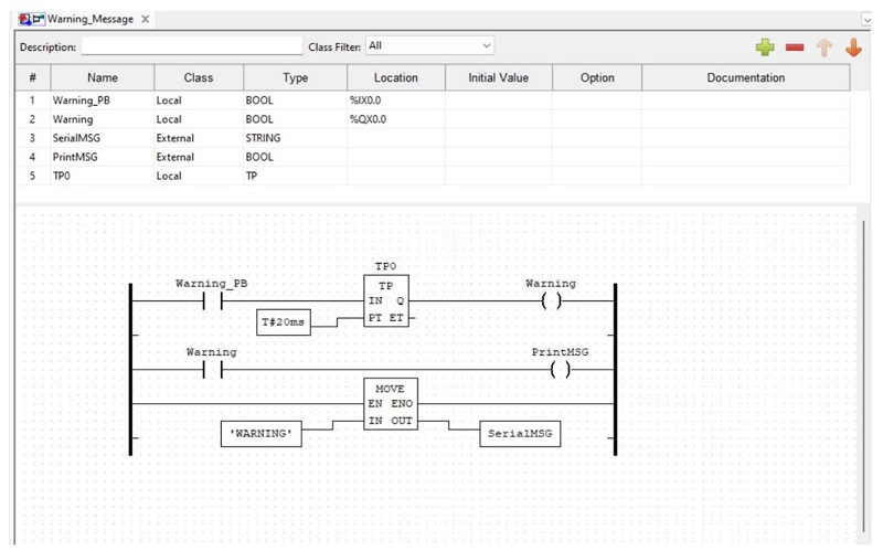
Figure 10. The project tag list and LD.
The Arduino extension to be included in our simulator project consists of three steps: adding the extension, defining the external tags, and providing the C++ code (the sketch). Figure 11 shows how to add the extension to the project.
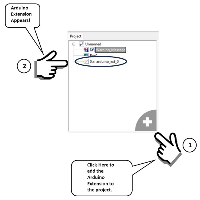
Figure 11. Adding an Arduino extension to the warning message simulator project.
The next steps are to define the tags and provide the sketch that allows text messages to be sent from the LD and received on a serial terminal. Figure 12 illustrates defining the variables in the tag listing and adding the C++ code for the extension.
After the tags and the LD have been built, download the ladder logic program to the Arduino PLC.
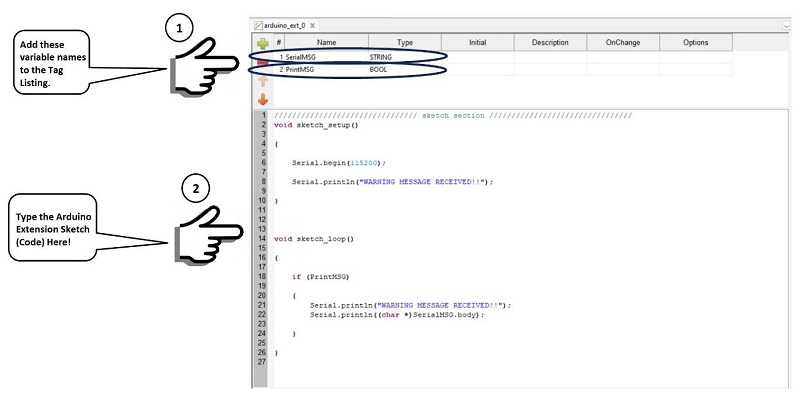
Figure 12. Defining tags and adding the Arduino sketch to the extension.
Setup and Display of The Serial Terminal
The built-in serial monitor in the Arduino IDE will work just fine with our message simulator, but it lacks the ability to log data into a file. This step is important when performing predictive maintenance using machine learning, which will be addressed in a future article.
The software that will be used in this activity and for future PdM and ML OpenPLC project activities is Tera Term. Download and install Tera Term to your programming computer, then open the software.
The first step is to establish a new connection with the Arduino Uno’s COM port, illustrated in Figure 13.
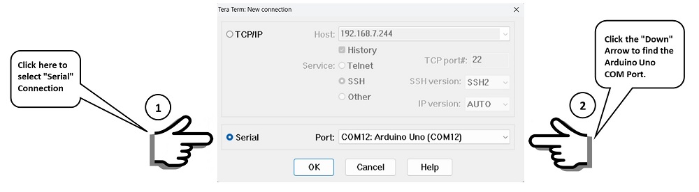
Figure 13. Establishing a serial connection.
To set up the connection, go to the top menu bar and select Setup>Serial Port. Set the COM port to where the Arduino is attached, change the baud rate to 115200, then click the ‘New Setting” button.
Now press the pushbutton on the breadboard to display the header information and the warning message on the serial terminal window.
Figure 14 illustrates this COM port setup and the output response.
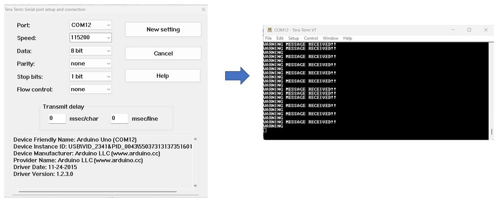
Figure 14. COM port setup and warning message output.
Two video clips illustrate the operation of our warning message project. This first video shows the LED response, while the second video, below, illustrates our new serial messaging capability.
The complete warning message simulator project file can be obtained from here.
This project opens a variety of control and monitoring possibilities for the Arduino PLC device. As illustrated, input events of sensors and switches can be monitored and displayed using the Arduino extension. The output status of devices like solenoids, motors, and visual indicators can be visualized on a serial terminal, just like LEDs, for remote monitoring. The PdM and ML approaches will be discussed in the next OpenPLC article.
All images and videos used courtesy of the author


This article starts out by listing the 5 languages in IEC 61131-3, but it only uses one: LD (ladder diagram). There is no ST (structured text) used. There is use of an Arduino extension and C++, but that’s not ST as defined by the IEC standard.