 Facebook
 Google
 GitHub
 Linkedin
Electricity and Electronics
AC Reactive Circuit Calculations
-
Question 1
Determine the input frequency necessary to give the output voltage a phase shift of 75$^{o}$:

Also, write an equation that solves for frequency ($f$), given all the other variables ($R$, $L$, and phase angle $\theta$).
Reveal answerKey Application for this Solution: RL Filter Phase Angle Equation
The fundamental phase angle equation relates resistance to induction in the following form:
$$ \tan \theta = {X_L \over R}$$
Since inductive reactance $X_L$ is equal to $2 \pi fL$ then the substituted phase angle equation is then:
$$ \tan \theta = {2 \pi fL \over R}$$
Solving this equation for frequency yields:
$$f = {R \tan \theta \over {2 \pi L}}$$
Finally, using the values provided, the actual frequency yields:
$$f = 157.970 kHz$$
Notes:Discuss with your students what a good procedure might be for calculating the unknown values in this problem, and also how they might check their work.
Students often have difficulty formulating a method of solution: determining what steps to take to get from the given conditions to a final answer. While it is helpful at first for you (the instructor) to show them, it is bad for you to show them too often, lest they stop thinking for themselves and merely follow your lead. A teaching technique I have found very helpful is to have students come up to the board (alone or in teams) in front of class to write their problem-solving strategies for all the others to see. They don’t have to actually do the math, but rather outline the steps they would take, in the order they would take them.
-
Question 2
An AC electric motor under load can be considered as a parallel combination of resistance and inductance:

Calculate the equivalent inductance ($L_{eq}$) if the measured source current is 27.5 amps and the motor’s equivalent resistance ($R_{eq}$) is 11.2 $\Omega$.
Reveal answerKey Application for this Solution: Inductive Load Effects
In AC parallel circuits, branch currents add in phasor fashion, which means the inductive current and resistive current form two sides of a right triangle. The resistive current may be calculated using Ohm’s Law ($I = {V \over R} = {277 \hbox{ V} \over 11.2 \> \Omega} = 24.73$ A):
The inductive current, therefore, may be calculated using the Pythagorean Theorem:
$${I_{total}}^2 = {I_R}^2 + {I_L}^2$$
$${I_L}^2 = {I_{total}}^2 - {I_R}^2$$
$$I_L = \sqrt{{I_{total}}^2 - {I_R}^2}$$
$$I_L = \sqrt{(27.5 \hbox{ A})^2 - (24.73 \hbox{ A})^2} = 12.02 \hbox{ A}$$
Knowing that the inductive current is 12.02 amps allows us to use Ohm’s Law to calculate the inductive reactance:
$$X = {V \over I}$$
$$X = {277 \hbox{ V} \over 12.02 \hbox{ A}} = 23.04 \> \Omega$$
Now we may calculate inductance from inductive reactance:
$$X_L = 2 \pi f L$$
$$L = {X_L \over 2 \pi f}$$
$$L = {23.04 \> \Omega \over (2 \pi) (60 \hbox{ Hz})} = 61.11 \hbox{ mH}$$
-
Question 3
An AC electric motor under load can be considered as a parallel combination of resistance and inductance:

Calculate the current necessary to power this motor if the equivalent resistance and inductance is 20 $\Omega$ and 238 $mH$, respectively.
Reveal answerKey Application for this Solution: Inductive Load Effects
In a parallel R-L circuit, the currents are added as the legs of a right triangle.
The resistance yields a current following Ohm’s Law:
$$I_R = {V \over R}$$
$$I_R = {240V \over 20 \Omega}$$
$$I_R = 12.0 A$$
Reactive current involves first determining the inductive reactance, then using Ohm’s Law:
$$X_L = 2 \pi f L$$
$$X_L = (2 \pi)(60Hz)(238mH)$$
$$X_L = 89.7 \Omega$$
Now use Ohm’s Law:
$$I_L = {V \over R}$$
$$I_L = {240V \over 89.7 \Omega}$$
$$I_L = 2.68 A$$
Finally, use the Pythagorean Equation to add the vector sums of the currents:
$$I_{supply} = \sqrt{(I_R)^2 + (I_L)^2}$$
$$I_{supply} = \sqrt{(12.0 A)^2 + (2.68 A)^2}$$
$$I_{supply} = 12.29 A$$
Notes:This is a practical example of a parallel LR circuit, as well as an example of how complex electrical devices may be “modeled” by collections of ideal components. To be honest, a loaded AC motor’s characteristics are quite a bit more complex than what the parallel LR model would suggest, but at least it’s a start!
Students often have difficulty formulating a method of solution: determining what steps to take to get from the given conditions to a final answer. While it is helpful at first for you (the instructor) to show them, it is bad for you to show them too often, lest they stop thinking for themselves and merely follow your lead. A teaching technique I have found very helpful is to have students come up to the board (alone or in teams) in front of class to write their problem-solving strategies for all the others to see. They don’t have to actually do the math, but rather outline the steps they would take, in the order they would take them. The following is a sample of a written problem-solving strategy for analyzing a series resistive-reactive AC circuit:
Step 1: Calculate all reactances ($X$).
Step 2: Draw an impedance triangle ($Z$ ; $R$ ; $X$), solving for $Z$
Step 3: Calculate circuit current using Ohm’s Law: $I = {V \over Z}$
Step 4: Calculate series voltage drops using Ohm’s Law: $V = {I Z}$
Step 5: Check work by drawing a voltage triangle ($V_{total}$ ; $V_1$ ; $V_2$), solving for $V_{total}$
By having students outline their problem-solving strategies, everyone gets an opportunity to see multiple methods of solution, and you (the instructor) get to see how (and if!) your students are thinking. An especially good point to emphasize in these “open thinking” activities is how to check your work to see if any mistakes were made.
-
Question 4
Calculate the individual currents through the inductor and through the resistor, the total current, and the total circuit impedance:

Also, draw a phasor diagram showing how the individual component currents relate to the total current.
Reveal answerKey Application for this Solution: Parallel RL Circuit Analysis
In a parallel R-L circuit, the currents are added as the legs of a right triangle.
The resistance yields a current following Ohm’s Law:
$$I_R = {V \over R}$$
$$I_R = {2.5V \over 5.1k \Omega}$$
$$I_R = 490.2 \mu A~RMS$$
Reactive current involves first determining the inductive reactance, then using Ohm’s Law:
$$X_L = 2 \pi f L$$
$$X_L = (2 \pi)(3kHz)(250mH)$$
$$X_L = 4.712k \Omega$$
Now use Ohm’s Law:
$$I_L = {V \over R}$$
$$I_L = {2.5V \over 4.712k \Omega}$$
$$I_L = 530.5 \mu A~RMS$$
Finally, use the Pythagorean Equation to add the vector sums of the currents:
$$I_{total} = \sqrt{(I_R)^2 + (I_L)^2}$$
$$I_{total} = \sqrt{(490.2 \mu A)^2 + (530.5 \mu A)^2}$$
$$I_{total} = 722.3 \mu A~RMS$$
Total impedance is found using Ohm’s Law again:
$$R~(or~Z) = {V \over I}$$
$$Z_{total} = {2.5V \over 722.3 \mu A}$$
$$Z_{total} = 3.461 k \Omega $$
Notes:This would be an excellent question to have students present methods of solution for. Sometimes I have students present nothing but their solution steps on the board in front of class (no arithmetic at all), in order to generate a discussion on problem-solving strategies. The important part of their education here is not to arrive at the correct answer or to memorize an algorithm for solving this type of problem, but rather how to {\it think} like a problem-solver, and how to methodically apply the math they know to the problem(s) at hand.
-
Question 5
Calculate the total impedances (complete with phase angles) for each of the following capacitor-resistor circuits:
 Reveal answer
Key Application for this Solution: RC Circuit Analysis
Each of these can be solved in a similar fashion, as long as the equivalent capacitance is first determined for each circuit.
For the series circuit in the top-right, the inverse of each capacitor is added to find the inverse of the total capacitance:
$${1 \over C_{total}} = {1 \over C_{1}}+ {1 \over C_{2}}+ ...$$
$$C_{total} = 0.0688 \mu F$$
In the lower right corner, parallel capacitor values are simply added:
$$ C_{total} = C_{1}+ C_{2}+ ...$$
$$C_{total} = 0.32 \mu F$$

Once these values are determined, the same procedure applies to all 4x circuits to determine capacitive reactance:
$$X_C={1 \over (2 \pi)(f)(C)}$$
Then, to determine the total impedance:
$$Z_{total}=\sqrt{R^2+{X_C}^2}$$
And finally, phase angle:
$$\theta = {tan}^{-1}{-X_C \over R}$$
Note: $X_C$ is negative in the above equation because the total overall reactance is $X_L-X_C$ when both components are present. When only capacitors are present, the phase angle is negative.
Notes:Have your students explain how they solved for each impedance, step by step. You may find different approaches to solving the same problem(s), and your students will benefit from seeing the diversity of solution techniques.
-
Question 6
Calculate the total impedances (complete with phase angles) for each of the following inductor-resistor circuits:
 Reveal answer
Key Application for this Solution: RL Circuit Analysis
Each of these can be solved in a similar fashion, as long as the equivalent capacitance is first determined for each circuit.
For the series circuit in the top-right, the inductor values are simply added to find the total inductance:
$$ L_{total} = L_{1}+ L_{2}+ ...$$
$$L_{total} = 1.2H$$
In the lower right corner, the inverse of each parallel inductor value is added to find the inverse f the total:
$${1 \over L_{total}} = {1 \over L_{1}}+ {1 \over L_{2}}+ ...$$
$$L_{total} = 0.167 H$$

Once these values are determined, the same procedure applies to all 4x circuits to determine inductive reactance:
$$X_L=(2 \pi)(f)(L)$$
Then, to determine the total impedance:
$$Z_{total}=\sqrt{R^2+{X_L}^2}$$
And finally, phase angle:
$$\theta = {tan}^{-1}{X_L \over R}$$
Notes:Have your students explain how they solved for each impedance, step by step. You may find different approaches to solving the same problem(s), and your students will benefit from seeing the diversity of solution techniques.
-
Question 7
Is this circuit’s overall behavior capacitive or inductive? In other words, from the perspective of the AC voltage source, does it “appear” as though a capacitor is being powered, or an inductor?

Now, suppose we take these same components and re-connect them in parallel rather than series. Does this change the circuit’s overall “appearance” to the source? Does the source now “see” an equivalent capacitor or an equivalent inductor? Explain your answer.
{\bullet} Which component “dominates” the behavior of a series LC circuit, the one with the least reactance or the one with the greatest reactance?
{\bullet} Which component “dominates” the behavior of a parallel LC circuit, the one with the least reactance or the one with the greatest reactance?Reveal answerKey Application for this Solution: LC Circuit Reactance
The first (series) circuit’s behavior is predominantly inductive, with 961.3 ohms of inductive reactance overshadowing 884.2 ohms of capacitive reactance, for a total circuit impedance of 77.13 ohms $\angle$ +90$^{o}$ (polar form) or 0 + j77.13 ohms (rectangular form).
The second (parallel) circuit’s behavior is capacitive, with 1.131 millisiemens of capacitive susceptance overshadowing 1.040 millisiemens of inductive susceptance, for a total circuit admittance of 90.74 microsiemens $\angle$ +90$^{o}$. This translates into a total circuit impedance of 11.02 k$\Omega$ $\angle$ $-90^{o}$, the negative phase angle clearly indicating this to be a predominantly capacitive circuit.
Notes:As usual, the real point of this question is to get students to think about the analytical procedure(s) they use, and to engage their minds in problem-solving behavior. Ask them why they think the circuits behave inductively or capacitively.
Students often have difficulty formulating a method of solution: determining what steps to take to get from the given conditions to a final answer. While it is helpful at first for you (the instructor) to show them, it is bad for you to show them too often, lest they stop thinking for themselves and merely follow your lead. A teaching technique I have found very helpful is to have students come up to the board (alone or in teams) in front of class to write their problem-solving strategies for all the others to see. They don’t have to actually do the math, but rather outline the steps they would take, in the order they would take them. The following is a sample of a written problem-solving strategy for analyzing a series resistive-reactive AC circuit:
Step 1: Calculate all reactances ($X$).
Step 2: Draw an impedance triangle ($Z$ ; $R$ ; $X$), solving for $Z$
Step 3: Calculate circuit current using Ohm’s Law: $I = {V \over Z}$
Step 4: Calculate series voltage drops using Ohm’s Law: $V = {I Z}$
Step 5: Check work by drawing a voltage triangle ($V_{total}$ ; $V_1$ ; $V_2$), solving for $V_{total}$
By having students outline their problem-solving strategies, everyone gets an opportunity to see multiple methods of solution, and you (the instructor) get to see how (and if!) your students are thinking. An especially good point to emphasize in these “open thinking” activities is how to check your work to see if any mistakes were made.
-
Question 8
Calculate the voltage dropped across the inductor, the capacitor, and the 8-ohm speaker in this sound system at the following frequencies, given a constant source voltage of 15 volts:
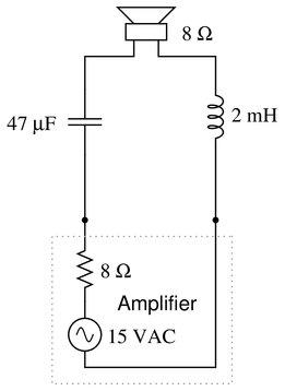 {\bullet} $f =$ 200 Hz
{\bullet} $f =$ 550 Hz
{\bullet} $f =$ 900 Hz
Regard the speaker as nothing more than an 8-ohm resistor.
{\bullet} As part of an audio system, would this LC network tend to emphasize the bass, treble, or mid-range tones?
Reveal answerKey Application for this Solution: RLC Series Circuit Analysis
Between each scenario, the only variable is the frequency, so let us solve the equation for the first frequency of 200 Hz, then use your calculator skills to substitute the other frequencies.
First, determine each of the $R$, $X_L$, and $X_C$ values:
$$R_{total}=R_{amp}+R_{speaker}$$
$$R_{total} = 16 \Omega$$
$$X_L=(2 \pi)(f)(L)$$
$$X_L=(2 \pi)(200Hz)(2mH)$$
$$X_L = 2.51 \Omega$$
$$X_C={1 \over (2 \pi)(f)(C)}$$
$$X_C={1 \over (2 \pi)(200Hz)(47 \mu F)}$$
$$X_C= 16.9 \Omega$$
Total circuit impedance is then:
$$Z_{total}=\sqrt{R^2+{X_L-X_C}^2}$$
$$Z_{total}=\sqrt {16^2+(-14.39)^2}$$
$$Z_{total}=21.5 \Omega$$
Current is found using Ohm’s Law:
$$I_{total}={V_{source} \over Z_{total}}$$
$$I_{total}=696mA$$
Since the current is equal across all components in a series circuits, multiply the current by each component’s impedance to find each respective voltage drop:
$$V_L=696mA \times 2.51 \Omega$$
$$V_C=696mA \times 16.9 \Omega$$
$$V_{speaker}=696mA \times 8 \Omega$$
- $f =$ 200 Hz ; $V_L =$ 1.750 V ; $V_C =$ 11.79 V ; $V_{speaker} =$ 5.572 V
- $f =$ 550 Hz ; $V_L =$ 6.472 V ; $V_C =$ 5.766 V ; $V_{speaker} =$ 7.492 V
- $f =$ 900 Hz ; $V_L =$ 9.590 V ; $V_C =$ 3.763 V ; $V_{speaker} =$ 6.783 V
This circuit is known as a midrange crossover in stereo system design.
Notes:This is an interesting circuit to analyze. Note how, out of the three frequency points we performed calculations at, the speaker’s voltage is greatest at the middle frequency. Note also how the inductor and capacitor drop very disparate amounts of voltage at the high and low frequencies. Discuss this circuit’s behavior with your students, and ask them what practical function this circuit performs.
-
Question 9
Write an equation that solves for the impedance of this series circuit. The equation need not solve for the phase angle between voltage and current, but merely provide a scalar figure for impedance (in ohms):
 Reveal answer
Key Application for this Solution: RLC Series Circuit Analysis
In any series AC circuit, the total impedance is the vector sum of resistance and reactance, which form a 90$^o$ phase relationship. As in any triangle with 90$^o$ between sides, the Pythagorean Theorem is the equation to identify the resultant vector sum.
The reactance in this series circuit arrangement is the result of the difference between $X_L$ and $X_C$. Since the voltage across the inductor leads the source voltage, and the voltage across the capacitor lags behind the source voltage, the effect is equal but opposite.
Both reactances act at 90$^o$ to the source, but in positive and negative directions, respectively. Therefore, total reactance is $X_L-X_C$ in a series AC circuit.
$$Z_{total} = \sqrt{R^2 + (X_L - X_C)^2}$$
Notes:Ask your students why one of the reactance terms under the radicand is positive and the other is negative. The way this equation is written, does it matter which term is negative? As your students if we would obtain the same answer if it were written as $Z_{total} = \sqrt{R^2 + (X_C - X_L)^2}$ instead. Challenge them to answer this question without using a calculator!
-
Question 10
Determine the necessary resistor value to give the output voltage a phase shift of 64$^{o}$:

Also, write an equation that solves for this resistance value ($R$), given all the other variables ($f$, $C$, and phase angle $\theta$).
Reveal answerKey Application for this Solution: RC Filter Phase Angle Equation
The fundamental phase angle equation relates resistance to capacitance in the following form:
$$ \tan \theta = {X_C \over R}$$
Since capacitive reactance $X_L$ is equal to ${1 \over 2 \pi fC}$ then the substituted phase angle equation is then:
$$ \tan \theta = {1 \over (2 \pi)(f)(C)(R)}$$
Solving this equation for resistance yields:
$$R = {1 \over (2 \pi)(f)(C)(\tan \theta)}$$
Finally, using the values provided, the actual resistance yields:
$$R = 5.1k \Omega$$
Note: technically, the phase angle is negative for RC circuits, and likewise, the phase angle equation uses $-R_C$, however, the resistance value will return a positive value in both cases.
Notes:Discuss with your students what a good procedure might be for calculating the unknown values in this problem, and also how they might check their work.
Students often have difficulty formulating a method of solution: determining what steps to take to get from the given conditions to a final answer. While it is helpful at first for you (the instructor) to show them, it is bad for you to show them too often, lest they stop thinking for themselves and merely follow your lead. A teaching technique I have found very helpful is to have students come up to the board (alone or in teams) in front of class to write their problem-solving strategies for all the others to see. They don’t have to actually do the math, but rather outline the steps they would take, in the order they would take them.
-
Question 11
Determine the necessary resistor value to give the output voltage a phase shift of 58$^{o}$:

Also, write an equation that solves for this resistance value ($R$), given all the other variables ($f$, $C$, and phase angle $\theta$).
Reveal answerKey Application for this Solution: RC Filter Phase Angle Equation
Using the same process as in the previous example:
$$ \tan \theta = {1 \over (2 \pi)(f)(C)(R)}$$
Solving this equation for resistance yields:
$$R = {1 \over (2 \pi)(f)(C)(\tan \theta)}$$
Finally, using the values provided, the actual resistance yields:
$$R = 669.7 \Omega$$
Notes:Discuss with your students what a good procedure might be for calculating the unknown values in this problem, and also how they might check their work.
Students often have difficulty formulating a method of solution: determining what steps to take to get from the given conditions to a final answer. While it is helpful at first for you (the instructor) to show them, it is bad for you to show them too often, lest they stop thinking for themselves and merely follow your lead. A teaching technique I have found very helpful is to have students come up to the board (alone or in teams) in front of class to write their problem-solving strategies for all the others to see. They don’t have to actually do the math, but rather outline the steps they would take, in the order they would take them.
-
Question 12
Determine the input frequency necessary to give the output voltage a phase shift of 25$^{o}$:
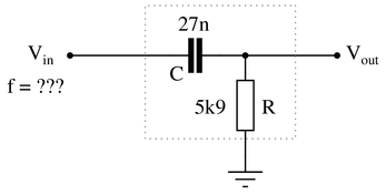
Also, write an equation that solves for frequency ($f$), given all the other variables ($R$, $C$, and phase angle $\theta$).
Reveal answerKey Application for this Solution: RC Filter Phase Angle Equation
Using the same process as in the previous examples, except this time, solving for the frequency:
$$ \tan \theta = {1 \over (2 \pi)(f)(C)(R)}$$
Solving this equation for resistance yields:
$$f = {1 \over (2 \pi)(R)(C)(\tan \theta)}$$
Finally, using the values provided, the actual frequency yields:
$$f = 2.143 kHz$$
Notes:Discuss with your students what a good procedure might be for calculating the unknown values in this problem, and also how they might check their work.
Students often have difficulty formulating a method of solution: determining what steps to take to get from the given conditions to a final answer. While it is helpful at first for you (the instructor) to show them, it is bad for you to show them too often, lest they stop thinking for themselves and merely follow your lead. A teaching technique I have found very helpful is to have students come up to the board (alone or in teams) in front of class to write their problem-solving strategies for all the others to see. They don’t have to actually do the math, but rather outline the steps they would take, in the order they would take them.
-
Question 13
Determine the input frequency necessary to give the output voltage a phase shift of 40$^{o}$:
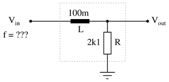
Also, write an equation that solves for frequency ($f$), given all the other variables ($R$, $L$, and phase angle $\theta$).
Reveal answerKey Application for this Solution: RL Filter Phase Angle Equation
The fundamental phase angle equation relates resistance to induction in the following form:
$$ \tan \theta = {X_L \over R}$$
Since inductive reactance $X_L$ is equal to $2 \pi fL$ then the substituted phase angle equation is then:
$$ \tan \theta = {2 \pi fL \over R}$$
Solving this equation for frequency yields:
$$f = {R \tan \theta \over {2 \pi L}}$$
Finally, using the values provided, the actual frequency yields:
$$f = 2.804 kHz$$
Notes:Discuss with your students what a good procedure might be for calculating the unknown values in this problem, and also how they might check their work.
Students often have difficulty formulating a method of solution: determining what steps to take to get from the given conditions to a final answer. While it is helpful at first for you (the instructor) to show them, it is bad for you to show them too often, lest they stop thinking for themselves and merely follow your lead. A teaching technique I have found very helpful is to have students come up to the board (alone or in teams) in front of class to write their problem-solving strategies for all the others to see. They don’t have to actually do the math, but rather outline the steps they would take, in the order they would take them.
-
Question 14
Calculate the total impedance offered by these two inductors to a sinusoidal signal with a frequency of 60 Hz:
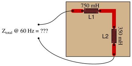
Show your work using two different problem-solving strategies:
{\bullet} Calculating total inductance ($L_{total}$) first, then total impedance ($Z_{total}$).
{\bullet} Calculating individual impedances first ($Z_{L1}$ and $Z_{L2}$), then total impedance ($Z_{total}$).Do these two strategies yield the same total impedance value? Why or why not?
Reveal answerKey Application for this Solution: Total Inductance and Impedance
First strategy:
$L_{total} = 1.1 \hbox{ H}$
$X_{total} = 414.7 \> \Omega$
${\bf Z_{total}} = 414.7 \> \Omega \> \angle \> 90^o$ or ${\bf Z_{total}} = 0 + j414.7 \> \Omega$
Second strategy:
$X_{L1} = 282.7 \> \Omega$ 10pt ${\bf Z_{L1}} = 282.7 \> \Omega \> \angle \> 90^o$
$X_{L2} = 131.9 \> \Omega$ 10pt ${\bf Z_{L2}} = 131.9 \> \Omega \> \angle \> 90^o$
${\bf Z_{total}} = 414.7 \> \Omega \> \angle \> 90^o$ or ${\bf Z_{total}} = 0 + j414.7 \> \Omega$
Notes:The purpose of this question is to get students to realize that any way they can calculate total impedance is correct, whether calculating total inductance and then calculating impedance from that, or by calculating the impedance of each inductor and then combining impedances to find a total impedance. This should be reassuring, because it means students have a way to check their work when analyzing circuits such as this!
-
Question 15
Determine the input frequency necessary to give the output voltage a phase shift of $25^{o}$:
 Reveal answer
Key Application for this Solution: RC Filter Phase Angle Equation
The fundamental phase angle equation relates resistance to capacitance in the following form:
$$ \tan \theta = {X_C \over R}$$
Since capacitive reactance $X_L$ is equal to ${1 \over 2 \pi fC}$ then the substituted phase angle equation is then:
$$ \tan \theta = {1 \over (2 \pi)(f)(C)(R)}$$
Solving this equation for resistance yields:
$$f = {1 \over (2 \pi)(R)(C)(\tan \theta)}$$
Finally, using the values provided, the actual frequency yields:
$$f = 4.27 kHz$$
Notes:Phase-shifting circuits are very useful, and important to understand. They are particularly important in some types of oscillator circuits, which rely on RC networks such as this to provide certain phase shifts to sustain oscillation.
-
Question 16
Determine the input frequency necessary to give the output voltage a phase shift of 40$^{o}$:
 Reveal answer
Key Application for this Solution: RC Filter Phase Angle Equation
The fundamental phase angle equation relates resistance to capacitance in the following form:
$$ \tan \theta = {X_C \over R}$$
Since capacitive reactance $X_L$ is equal to ${1 \over 2 \pi fC}$ then the substituted phase angle equation is then:
$$ \tan \theta = {1 \over (2 \pi)(f)(C)(R)}$$
Solving this equation for resistance yields:
$$f = {1 \over (2 \pi)(R)(C)(\tan \theta)}$$
Finally, using the values provided, the actual frequency yields:
$$f = 6.54 kHz$$
Notes:Phase-shifting circuits are very useful, and important to understand. They are particularly important in some types of oscillator circuits, which rely on RC networks such as this to provide certain phase shifts to sustain oscillation.
-
Question 17
A student is asked to calculate the phase shift for the following circuit’s output voltage, relative to the phase of the source voltage:

He recognizes this as a series circuit, and therefore realizes that a right triangle would be appropriate for representing component impedances and component voltage drops (because both impedance and voltage are quantities that add in series, and the triangle represents phasor addition):
The problem now is, which angle does the student solve for in order to find the phase shift of $V_{out}$? The triangle contains two angles besides the 90$^{o}$ angle, $\theta$ and $\Phi$. Which one represents the output phase shift, and more importantly, why?
Reveal answerKey Application for this Solution: RC Filter Phase Angle Equation
The proper angle in this circuit is $\theta$, and it will be a positive (leading) quantity.
The reason we must focus on $\theta$ in this problem is because this is the angle separating the resistor’s voltage drop from the source’s voltage. Note how in the circuit $V_{out}$ is measured across the resistor, not across the capacitor.
Notes:Too many students blindly use impedance and voltage triangles without really understand what they are and why they work. These same students will have no idea how to approach a problem like this. Work with them to help them understand!
-
Question 18
Determine the total current and all voltage drops in this circuit, stating your answers the way a multimeter would register them:
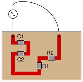
{\bullet} $C_1 = 125 \hbox{ pF}$
{\bullet} $C_2 = 71 \hbox{ pF}$
{\bullet} $R_1 = 6.8 \hbox{ k}\Omega$
{\bullet} $R_2 = 1.2 \hbox{ k}\Omega$
{\bullet} $V_{supply} = 20 \hbox{ V RMS}$
{\bullet} $f_{supply} = 950 \hbox{ kHz}$Also, calculate the phase angle ($\theta$) between voltage and current in this circuit, and explain where and how you would connect an oscilloscope to measure that phase shift.
Reveal answerKey Application for this Solution: RC Series Circuit Analysis
{\bullet} $I_{total} = 2.269 \hbox{ mA}$
{\bullet} $V_{C1} = 3.041 \hbox{ V}$
{\bullet} $V_{C2} = 5.354 \hbox{ V}$
{\bullet} $V_{R1} = 15.43 \hbox{ V}$
{\bullet} $V_{R2} = 2.723 \hbox{ V}$
{\bullet} $\theta = -24.82^o$ (voltage lagging current)I suggest using a dual-trace oscilloscope to measure total voltage (across the supply terminals) and voltage drop across resistor R_2. Theoretically, measuring the voltage dropped by either resistor would be fine, but R_2 works better for practical reasons (oscilloscope input lead grounding). Phase shift then could be measured either in the time domain or by a Lissajous figure analysis.
Notes:Some students many wonder what type of numerical result best corresponds to a multimeter’s readings, if they do their calculations using complex numbers (“do I use polar or rectangular form, and if rectangular do I use the real or the imaginary part?”). The answers given for this question should clarify that point.
It is very important that students know how to apply this knowledge of AC circuit analysis to real-world situations. Asking students to determine how they would connect an oscilloscope to the circuit to measure $\theta$ is an exercise in developing their abstraction abilities between calculations and actual circuit scenarios.
It is noteworthy that the low capacitances shown here approach parasitic capacitances between circuit board traces. In other words, whoever designs a circuit to operate at 950 kHz cannot simply place components at will on the board, but must consider the traces themselves to be circuit elements (both capacitive and inductive in nature!). The calculations used to obtain the given answers, of course, assume ideal conditions where the PC board is not considered to possess capacitance or inductance.
Students often have difficulty formulating a method of solution: determining what steps to take to get from the given conditions to a final answer. While it is helpful at first for you (the instructor) to show them, it is bad for you to show them too often, lest they stop thinking for themselves and merely follow your lead. A teaching technique I have found very helpful is to have students come up to the board (alone or in teams) in front of class to write their problem-solving strategies for all the others to see. They don’t have to actually do the math, but rather outline the steps they would take, in the order they would take them. The following is a sample of a written problem-solving strategy for analyzing a series resistive-reactive AC circuit:
Step 1: Calculate all reactances ($X$).
Step 2: Draw an impedance triangle ($Z$ ; $R$ ; $X$), solving for $Z$
Step 3: Calculate circuit current using Ohm’s Law: $I = {V \over Z}$
Step 4: Calculate series voltage drops using Ohm’s Law: $V = {I Z}$
Step 5: Check work by drawing a voltage triangle ($V_{total}$ ; $V_1$ ; $V_2$), solving for $V_{total}$
By having students outline their problem-solving strategies, everyone gets an opportunity to see multiple methods of solution, and you (the instructor) get to see how (and if!) your students are thinking. An especially good point to emphasize in these “open thinking” activities is how to check your work to see if any mistakes were made.
-
Question 19
Solve for all voltages and currents in this series RC circuit, and also calculate the phase angle of the total impedance:
 Reveal answer
Key Application for this Solution: RC Series Circuit Analysis
For any RLC circuit (even if C of L are not present), the following process can be used:
First, determine each of the $R$, $X_L$, and $X_C$ values:
$$R_{total}=R$$
$$R_{total} = 3.3k \Omega$$
$$X_L=0~(no~inductor~present)$$
$$X_C={1 \over (2 \pi)(f)(C)}$$
$$X_C={1 \over (2 \pi)(30Hz)(220 nF)}$$
$$X_C= 24.1k \Omega$$
Total circuit impedance is then:
$$Z_{total}=\sqrt{R^2+{X_L-X_C}^2}$$
$$Z_{total}=\sqrt {3.3k^2+(0-24.1k)^2}$$
$$Z_{total}=24.34k \Omega$$
Current is found using Ohm’s Law:
$$I_{total}={V_{source} \over Z_{total}}$$
$$I_{total}=1.97mA~Peak$$
Since the current is equal across all components in a series circuits, multiply the current by each component’s impedance to find each respective voltage drop:
$$V_C=1.97mA \times 24.1k \Omega$$
$$V_R=1.97mA \times 3.3k \Omega$$
$$V_C = 47.56V~Peak$$
$$V_R = 6.51V~Peak$$
Phase angle is found using either the voltage or impedance of the capacitor and resistor:
$$\theta_Z = \tan^{-1}{24.1k \Omega \over 3.3 k \Omega}$$
$$\theta_Z = 82.21^o$$
$$\theta_Z = \tan^{-1}{47.56V \over 6.51V}$$
$$\theta_Z = 82.21^o$$
Note: Both angles should be negative for a capacitive circuit.
Notes:Bring to your students’ attention the fact that total voltage in this circuit is given in “peak” units rather than RMS, and what effect this has on our answers.
Students often have difficulty formulating a method of solution: determining what steps to take to get from the given conditions to a final answer. While it is helpful at first for you (the instructor) to show them, it is bad for you to show them too often, lest they stop thinking for themselves and merely follow your lead. A teaching technique I have found very helpful is to have students come up to the board (alone or in teams) in front of class to write their problem-solving strategies for all the others to see. They don’t have to actually do the math, but rather outline the steps they would take, in the order they would take them. The following is a sample of a written problem-solving strategy for analyzing a series resistive-reactive AC circuit:
Step 1: Calculate all reactances ($X$).
Step 2: Draw an impedance triangle ($Z$ ; $R$ ; $X$), solving for $Z$
Step 3: Calculate circuit current using Ohm’s Law: $I = {V \over Z}$
Step 4: Calculate series voltage drops using Ohm’s Law: $V = {I Z}$
Step 5: Check work by drawing a voltage triangle ($V_{total}$ ; $V_1$ ; $V_2$), solving for $V_{total}$
By having students outline their problem-solving strategies, everyone gets an opportunity to see multiple methods of solution, and you (the instructor) get to see how (and if!) your students are thinking. An especially good point to emphasize in these “open thinking” activities is how to check your work to see if any mistakes were made.
-
Question 20
Solve for all voltages and currents in this series RC circuit:
 Reveal answer
Key Application for this Solution: RC Series Circuit Analysis
For any RLC circuit (even if C of L are not present), the following process can be used:
First, determine each of the $R$, $X_L$, and $X_C$ values:
$$R_{total}=R$$
$$R_{total} = 4.7k \Omega$$
$$X_L=0~(no~inductor~present)$$
$$X_C={1 \over (2 \pi)(f)(C)}$$
$$X_C={1 \over (2 \pi)(1kHz)(.01 \mu F)}$$
$$X_C= 15.9k \Omega$$
Total circuit impedance is then:
$$Z_{total}=\sqrt{R^2+{X_L-X_C}^2}$$
$$Z_{total}=\sqrt {4.7k^2+(0-15.9k)^2}$$
$$Z_{total}=16.59k \Omega$$
Current is found using Ohm’s Law:
$$I_{total}={V_{source} \over Z_{total}}$$
$$I_{total}=0.9mA~RMS$$
Since the current is equal across all components in a series circuits, multiply the current by each component’s impedance to find each respective voltage drop:
$$V_C=0.9mA \times 15.9k \Omega$$
$$V_R=0.9mA \times 4.7k \Omega$$
$$V_C = 14.39V~RMS$$
$$V_R = 4.25V~RMS$$
Notes:Nothing special here—just a straightforward exercise in series AC circuit calculations.
Students often have difficulty formulating a method of solution: determining what steps to take to get from the given conditions to a final answer. While it is helpful at first for you (the instructor) to show them, it is bad for you to show them too often, lest they stop thinking for themselves and merely follow your lead. A teaching technique I have found very helpful is to have students come up to the board (alone or in teams) in front of class to write their problem-solving strategies for all the others to see. They don’t have to actually do the math, but rather outline the steps they would take, in the order they would take them. The following is a sample of a written problem-solving strategy for analyzing a series resistive-reactive AC circuit:
Step 1: Calculate all reactances ($X$).
Step 2: Draw an impedance triangle ($Z$ ; $R$ ; $X$), solving for $Z$
Step 3: Calculate circuit current using Ohm’s Law: $I = {V \over Z}$
Step 4: Calculate series voltage drops using Ohm’s Law: $V = {I Z}$
Step 5: Check work by drawing a voltage triangle ($V_{total}$ ; $V_1$ ; $V_2$), solving for $V_{total}$
By having students outline their problem-solving strategies, everyone gets an opportunity to see multiple methods of solution, and you (the instructor) get to see how (and if!) your students are thinking. An especially good point to emphasize in these “open thinking” activities is how to check your work to see if any mistakes were made.
-
Question 21
Solve for all voltages and currents in this series LR circuit, and also calculate the phase angle of the total impedance:
 Reveal answer
Key Application for this Solution: RL Series Circuit Analysis
For any RLC circuit (even if C of L are not present), the following process can be used:
First, determine each of the $R$, $X_L$, and $X_C$ values:
$$R_{total}=R$$
$$R_{total} = 5k \Omega$$
$$X_L=(2 \pi)(50)(10.3)$$
$$X_L=(2 \pi)(f)(L)$$
$$X_L=3.2k \Omega$$
$$X_C=0~(no~capacitor~present)$$
Total circuit impedance is then:
$$Z_{total}=\sqrt{R^2+{X_L-X_C}^2}$$
$$Z_{total}=\sqrt {5k^2+(3.2k-0)^2}$$
$$Z_{total}=5.96k \Omega$$
Current is found using Ohm’s Law:
$$I_{total}={V_{source} \over Z_{total}}$$
$$I_{total}=4.03mA~RMS$$
Since the current is equal across all components in a series circuits, multiply the current by each component’s impedance to find each respective voltage drop:
$$V_L=4.03mA \times 3.2k \Omega$$
$$V_R=4.03mA \times 5k \Omega$$
$$V_L = 13.04V~RMS$$
$$V_R = 20.15V~RMS$$
Phase angle is found using either the voltage or impedance of the capacitor and resistor:
$$\theta_Z = \tan^{-1}{3.2k \Omega \over 5k \Omega}$$
$$\theta_Z = 32.91^o$$
$$\theta_Z = \tan^{-1}{13.04V \over 20.15V}$$
$$\theta_Z = 32.91^o$$
Notes:Nothing special here—just a straightforward exercise in series AC circuit calculations.
Students often have difficulty formulating a method of solution: determining what steps to take to get from the given conditions to a final answer. While it is helpful at first for you (the instructor) to show them, it is bad for you to show them too often, lest they stop thinking for themselves and merely follow your lead. A teaching technique I have found very helpful is to have students come up to the board (alone or in teams) in front of class to write their problem-solving strategies for all the others to see. They don’t have to actually do the math, but rather outline the steps they would take, in the order they would take them. The following is a sample of a written problem-solving strategy for analyzing a series resistive-reactive AC circuit:
Step 1: Calculate all reactances ($X$).
Step 2: Draw an impedance triangle ($Z$ ; $R$ ; $X$), solving for $Z$
Step 3: Calculate circuit current using Ohm’s Law: $I = {V \over Z}$
Step 4: Calculate series voltage drops using Ohm’s Law: $V = {I Z}$
Step 5: Check work by drawing a voltage triangle ($V_{total}$ ; $V_1$ ; $V_2$), solving for $V_{total}$
By having students outline their problem-solving strategies, everyone gets an opportunity to see multiple methods of solution, and you (the instructor) get to see how (and if!) your students are thinking. An especially good point to emphasize in these “open thinking” activities is how to check your work to see if any mistakes were made.
-
Question 22
Due to the effects of a changing electric field on the dielectric of a capacitor, some energy is dissipated in capacitors subjected to AC. Generally, this is not very much, but it is there. This dissipative behavior is typically modeled as a series-connected resistance:
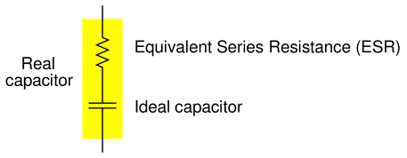
Calculate the magnitude and phase shift of the current through this capacitor, taking into consideration its equivalent series resistance (ESR):
Compare this against the magnitude and phase shift of the current for an ideal 0.22 $\mu$F capacitor.
Reveal answerKey Application for this Solution: RC Circuit Equivalent Series Resistance (ESR)
${\bf I} =$ 3.732206 mA $\angle$ 89.89$^{o}$ for the real capacitor with ESR.
${\bf I} =$ 3.732212 mA $\angle$ 90.00$^{o}$ for the ideal capacitor.
Notes:Although capacitors do contain their own parasitic effects, ESR being one of them, they still tend to be much “purer” components than inductors for general use. This is another reason why capacitors are generally favored over inductors in applications where either will suffice.
-
Question 23
Which component, the resistor or the capacitor, will drop more voltage in this circuit?

Also, calculate the total impedance ($Z_{total}$) of this circuit, expressing it in both rectangular and polar forms.
Reveal answerKey Application for this Solution: RC Series Circuit Analysis
The resistor will drop more voltage.
$Z_{total}$ (rectangular form) = 5100 $\Omega$ $-$ j4671 $\Omega$
$Z_{total}$ (polar form) = 6916 $\Omega$ $\angle$ $-42.5^{o}$
Notes:Ask your students how they were able to make the determination of greater voltage drop. Which method yields the fastest solution (i.e. requires the fewest steps)?
-
Question 24
Calculate all voltages and currents in this circuit, as well as the total impedance:
 Reveal answer
Key Application for this Solution: RL Series Circuit Analysis
First, determine each of the $R$, $X_L$, and $X_C$ values:
$$R_{total}=R$$
$$R_{total} = 5.1k \Omega$$
$$X_L=(2 \pi)(f)(L)$$
$$X_L=(2 \pi)(3000)(0.250)$$
$$X_L=4.7k \Omega$$
$$X_C=0~(no~capacitor~present)$$
Total circuit impedance is then:
$$Z_{total}=\sqrt{R^2+{X_L-X_C}^2}$$
$$Z_{total}=\sqrt {5.1k^2+(4.7k-0)^2}$$
$$Z_{total}=6.94k \Omega$$
Current is found using Ohm’s Law:
$$I_{total}={V_{source} \over Z_{total}}$$
$$I_{total}=4.90mA~RMS$$
Since the current is equal across all components in a series circuits, multiply the current by each component’s impedance to find each respective voltage drop:
$$V_L=4.90mA \times 4.7k \Omega$$
$$V_R=4.90mA \times 5.1k \Omega$$
$$V_L = 23.07V~RMS$$
$$V_R = 24.97V~RMS$$
Notes:This would be an excellent question to have students present methods of solution for. Sometimes I have students present nothing but their solution steps on the board in front of class (no arithmetic at all), in order to generate a discussion on problem-solving strategies. The important part of their education here is not to arrive at the correct answer or to memorize an algorithm for solving this type of problem, but rather how to think like a problem-solver, and how to methodically apply the math they know to the problem(s) at hand.
-
Question 25
Use the “impedance triangle” to calculate the necessary reactance of this series combination of resistance ($R$) and inductive reactance ($X$) to produce the desired total impedance of 145 $\Omega$:

Explain what equation(s) you use to calculate $X$, and the algebra necessary to achieve this result from a more common formula.
Reveal answerKey Application for this Solution: Impedance Triangle
$X$ = 105 $\Omega$, as calculated by an algebraically manipulated version of the Pythagorean Theorem:
$$X=\sqrt{Z^2-R^2}$$
Notes:Be sure to have students show you the form of the Pythagorean Theorem, rather than showing them yourself, since it is so easy for students to research on their own.
-
Question 26
Use the “impedance triangle” to calculate the impedance of this series combination of resistance ($R$) and inductive reactance ($X$):

Explain what equation(s) you use to calculate $Z$.
Reveal answerKey Application for this Solution: Impedance Triangle
$Z$ = 625 $\Omega$, as calculated directly by the Pythagorean Theorem:
$$Z=\sqrt{R^2+X^2}$$
Notes:Be sure to have students show you the form of the Pythagorean Theorem, rather than showing them yourself, since it is so easy for students to research on their own.
