Facebook
 Google
 GitHub
 Linkedin
Electricity and Electronics
Basic Circuit Troubleshooting
-
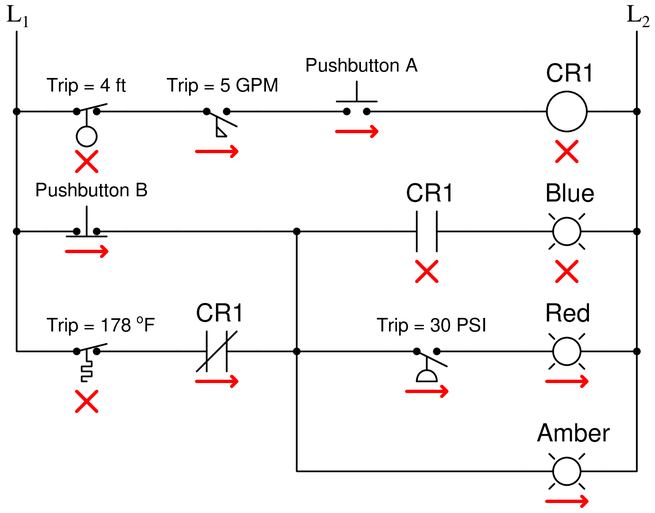
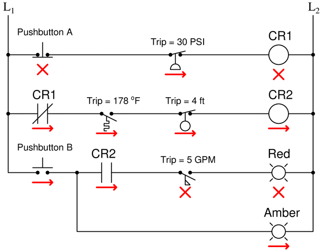
Question 1
Determine the statuses of all lamps and relay coils in this circuit, given the following process conditions:

{\bullet} Flow = 3.5 GPM
{\bullet} Pressure = 41 PSI
{\bullet} Temperature = 155 °F
{\bullet} Level = 1.3 ft
{\bullet} Pushbutton A = unpressed
{\bullet} Pushbutton B = unpressedReveal answerFully annotated circuit schematic:
“X” represents an open contact or de-energized load
“{\rightarrow}” represents a closed contact or energized load}
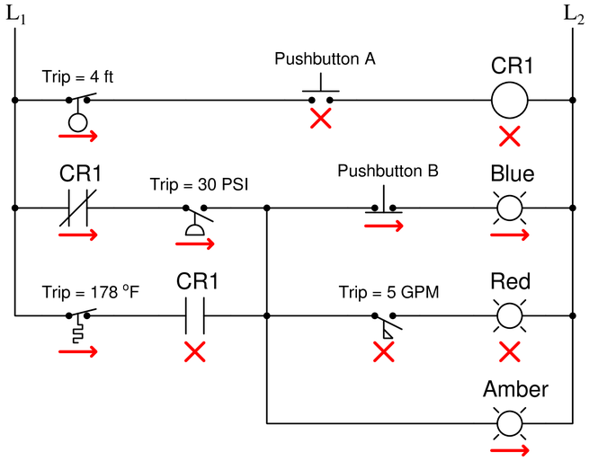
Recall that a process switch will be in its resting (“normal”) condition when the stimulus value is less than the trip threshold, and will be in its actuated condition when the stimulus exceeds the threshold.
Therefore,
{\bullet} CR1 coil = de-energized
{\bullet} Blue lamp = energized
{\bullet} Red lamp = de-energized
{\bullet} Amber lamp = energizedNotes:Reference educational links:
- Relay circuits and ladder diagrams
- Ladder diagram structures
- NO and NC electrical symbols
- Understanding NO and NC contacts
-
Question 2
A form of liquid level switch called a tilt switch is often used for detecting sewage level in “lift stations” where sewage collected from homes via gravity is pumped out of the collection sump to the wastewater treatment plant (usually located miles away):
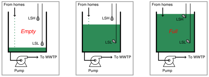
Tilt switches often use a small glass vial containing liquid mercury as the tilt sensor. Explain how a glass tube partially filled with mercury works as an electrical tilt switch, and also perform a “thought experiment” where you describe this system’s function from start to finish through a complete start-stop cycle of the pump motor:
{\bullet} What would happen if the OL switch failed open in this system?
{\bullet} What would happen if the LSL switch failed open in this system?
{\bullet} What would happen if the LSH switch failed open in this system?
{\bullet} What would happen if the LSL switch failed shorted in this system?
{\bullet} What would happen if the LSH switch failed shorted in this system?
{\bullet} What would happen if the LSH switch failed shorted in this system?
{\bullet} What would happen if the M1 seal-in contact failed open in this system?
{\bullet} What would happen if the M1 seal-in contact failed shorted in this system?Reveal answerA mercury “tilt switch” uses a sample of liquid mercury metal to bridge wire contacts inside of a sealed glass tube when the tube is tipped in a certain direction.
Thought experiment:
{\bullet} Sump starts empty
{\bullet} Level begins to rise
{\bullet} LSL switch tilts; motor doesn’t start up yet because LSH is still open
{\bullet} LSH switch tilts; motor starts up
{\bullet} Level begins to drop as pump moves wastewater out of sump
{\bullet} LSH returns to normal; motor continues to run because it’s control circuit is “sealed in”
{\bullet} LSL retuns to normal; motor stops and remains off until LSH tips againPredicting the effect of a given fault:
Present each of the following faults to the students, one at a time, having them comment on all the effects each fault would produce.
Identifying possible/impossible faults:
Present symptoms to the students and then have them determine whether or not a series of suggested faults could account for all the symptoms, explaining why or why not for each proposed fault:
{\bullet} Symptom:
{\bullet} — Yes/No
{\bullet} — Yes/No
{\bullet} — Yes/NoDetermining the utility of given diagnostic tests:
Present symptoms to the students and then propose the following diagnostic tests one by one. Students rate the value of each test, determining whether or not it would give useful information (i.e. tell us something we don’t already know). Students determine what different results for each test would indicate about the fault, if anything:
{\bullet} Symptom:
{\bullet} — Yes/No
{\bullet} — Yes/NoDiagnosing a fault based on given symptoms:
Imagine the LSH fails shorted in this system (don’t reveal the fault to students!). Present the operator’s observation(s) to the students, have them consider possible faults and diagnostic strategies, and then tell them the results of tests they propose based on the following symptoms, until they have properly identified the nature and location of the fault:
{\bullet} The pump keeps cycling on and off at the low-level switch’s height.
Notes:Be sure to review the operation of the simple motor start-stop circuit in your answer!
————————
Reference educational links:
-
Question 3
Draw a ladder logic control circuit for the electric motor of an air compressor, controlled by two pressure switches: one switch turns the motor on when the pressure falls to 80 PSI, while the other switch turns the motor off when the pressure rises to 105 PSI:

Be sure to include the overload (OL) contact in the 120 volt control circuit (L1 & L2), and include a manual on/off switch as well.
-
Question 4
Some common components of three-phase motor control circuits are shown here in the following illustrations. These include fuses, a contactor, and an overload assembly:
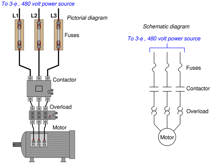
Fuses protect the power wiring from gross overcurrent conditions such as what might happen if there were an accidental phase-to-phase short-circuit inside the motor. The contactor is nothing more than a big relay with three normally-open contacts to send power to the motor, serving to start and stop the motor on command with a 120 volt signal to its coil.
The overload block, however, is a little more mysterious. Its three “heater” elements (looking like back-to-back “question mark” symbols in the schematic diagram) carry the motor’s current from the contactor to the motor terminals. These resistive heaters are designed to become warm under normal operating conditions, just as the motor itself will become slightly warm under normal conditions from resistive power losses in its windings.
If the motor ever becomes too warm as a result of overloading (slight overcurrent), the overload heaters (which will also be too warm due to the overcurrent) will trigger a small thermally-operated switch contact to spring open. Connection terminals for this small switch contact may be seen on the right-hand side of the overload block in the pictorial diagram.
Explain how the overload heaters may be used to automatically shut the motor off and prevent damage.
Reveal answerIf you thought the overload heaters would open up like fuses in the event of an overload condition (becoming too warm) to directly interrupt motor current, you have made a very common error!
Don’t feel bad, though—I won’t tell anyone.
The OL contact is always wired in series with the contactor coil to tell the contactor to open in the event of an overload.
When the overload “heaters” become excessively warm from overcurrent, they trigger the opening of the “OL” contact, thus stopping the motor. The heaters do not take the place of regular overcurrent protection devices (circuit breakers, fuses), but serve a different purpose entirely. It is the task of the overload heaters to protect the {\it motor} against overcurrent by mimicking the thermal characteristics of the motor itself. Circuit breakers and fuses, on the other hand, protect the wiring conveying power to the motor!
An interesting way to explain the function of overload heaters is to refer to them as somewhat analogous to the motor windings. They are designed such that at any given current level, they will take as long to heat up and reach their trip point as the real motor itself will take to heat up to a point of impending damage. Likewise, they also cool off at the same rate as the real motor cools off when no power is applied. Overload heaters are like small motor-models with a thermostat mechanism attached, to trip the overload contact at the appropriate time. It is an elegant concept, and quite practical in real motor control applications.
Notes:Reference educational links:
-
Question 5
Explain the operation of this circuit:
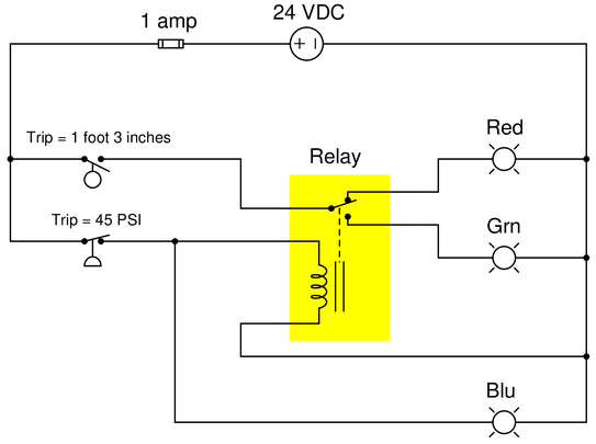 Reveal answer
The blue lamp will be energized whenever the pressure switch senses a pressure that is less than 45 PSI.
The red and green lamps will both be de-energized whenever the level senses a level less than 1 foot 3 inches. If that switch senses a level greater than 1 foot 3 inches, either the red lamp or the green lamp will energize (not both simultaneously!) based on the pressure switch’s state: a pressure less than 45 PSI energizes the relay coil and energizes the green lamp, while a pressure greater than 45 PSI de-energizes the relay coil and energizes the red lamp.
Notes:Predicting the effect of a given fault:
Present each of the following faults to the students, one at a time, having them comment on all the effects each fault would produce.
Identifying possible/impossible faults:
Present symptoms to the students and then have them determine whether or not a series of suggested faults could account for all the symptoms, explaining why or why not for each proposed fault:
{\bullet} Symptom: Level = 2 ft and Pressure = 24 PSI; blue and red lights are energized
{\bullet} Open relay contact— No
{\bullet} Open relay coil— Yes
{\bullet} Open pressure switch— No
{\bullet} Open level switch— No
{\bullet} Open fuse— No
{\bullet} Open wire between fuse and pressure switch— No
{\bullet} Open wire between relay coil and pressure switch— Yes
{\bullet} Open wire between relay coil and negative rail— YesDetermining the utility of given diagnostic tests:
Present symptoms to the students and then propose the following diagnostic tests one by one. Students rate the value of each test, determining whether or not it would give useful information (i.e. tell us something we don’t already know). Students determine what different results for each test would indicate about the fault, if anything:
{\bullet} Symptom:
{\bullet} — Yes/No
{\bullet} — Yes/NoDiagnosing a fault based on given symptoms:
Imagine the ??? fails ??? in this system (don’t reveal the fault to students!). Present the operator’s observation(s) to the students, have them consider possible faults and diagnostic strategies, and then tell them the results of tests they propose based on the following symptoms, until they have properly identified the nature and location of the fault:
-
Question 6
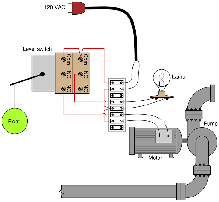
Sketch the necessary wiring to make this float-type level switch control a pump and a lamp in the following manner:
{\bullet} High liquid level: pump on and lamp off
{\bullet} Low liquid level: pump off and lamp on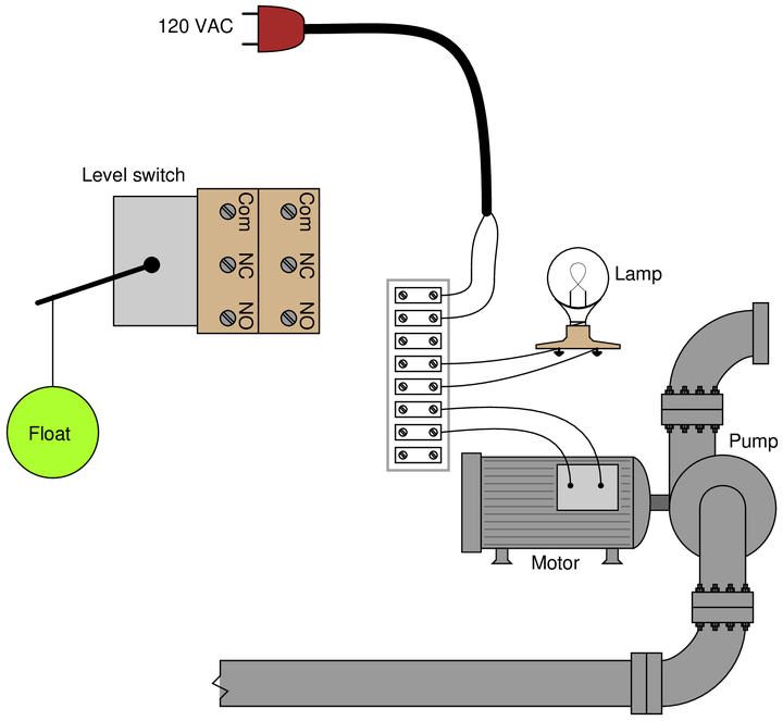
Hint: remember that the “normal” status of a switch is defined as the status of minimum stimulus when the switch is exposed to the lowest possible degree of process stimulation (in this particular case, to the lowest possible level).
Reveal answerThis is just one possible solution:
 Notes:
Reference educational links:
-
Question 7
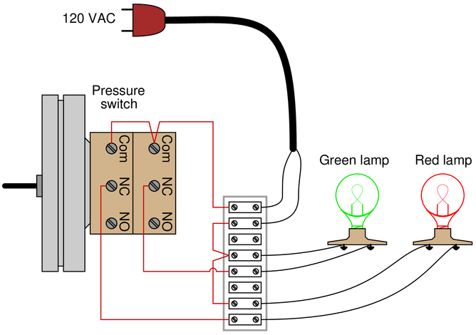
Sketch the necessary wiring to make this pressure switch control two lamps in the following manner:
{\bullet} High process pressure: green lamp off and red lamp off
{\bullet} Low process pressure: red lamp on and green lamp on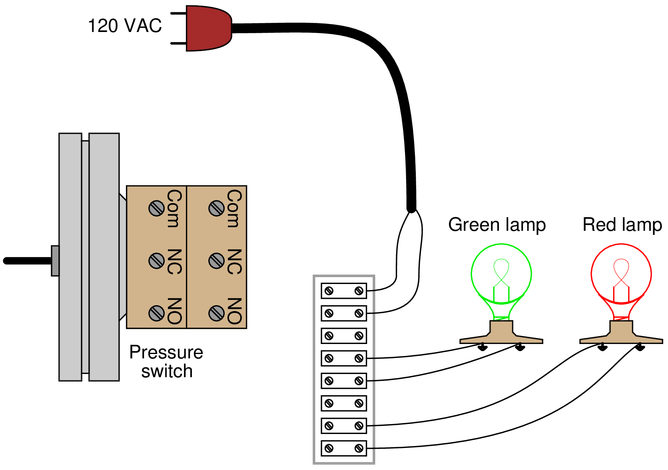
Hint: remember that the “normal” status of a switch is defined as the status of minimum stimulus when the switch is exposed to the lowest possible degree of process stimulation (in this particular case, to the lowest possible pressure).
Reveal answerThis is just one possible solution:
 Notes:
Reference educational links:
-
Question 8
Examine the following electronic level switch circuit:
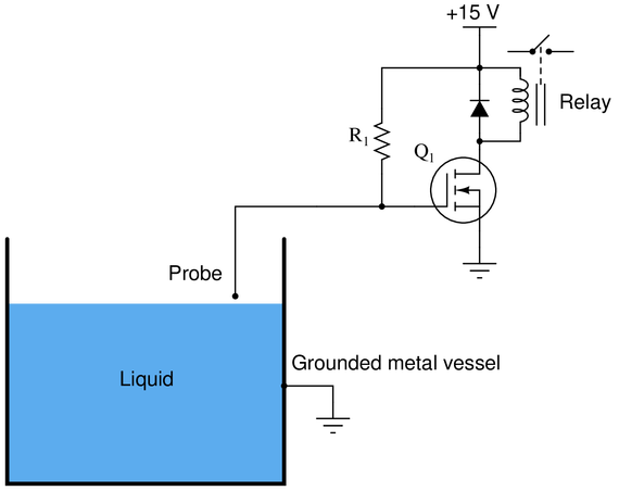
Identify what kinds of process liquids this level switch would be applicable to, and why. Also, identify which ladder-logic switch symbol would be appropriate for this particular level switch:
Qualitatively determine the following component voltage drops in the circuit with low level and with high level (i.e. write “low” or “high” voltage rather than try to calculate actual values):
$$\begin{array} {|l|l|}\hline Component & Low-level~condition & High-level~condition \\ \hline R1 & & \\ \hline Q1~(between~drain~and~source) & & \\ \hline \end{array}$$
Reveal answerAn important fact to recall regarding MOSFET transistors is that this is an E-type (enhancement-type) MOSFET, and as such is normally-off. Being an N-channel MOSFET, a positive gate signal is required to turn it on. Specifically, the applied gate voltage must be of such a polarity that the gate is more positive than the transistor substrate. This will turn the MOSFET on and allow current to go through to the relay coil to energize it and close the switch contacts.
A resistor connecting the MOSFET’s gate terminal to the +15 volt power supply rail provides the necessary bias to turn the transistor on when no liquid touches the probe. This energizes the relay and closes the switch contacts, so that the contacts are closed when the probe is dry. This, by definition, is a normally-closed liquid level switch.
When liquid level rises up high enough to contact the probe, it shorts the probe to ground. This forces the MOSFET gate to a zero-volt condition, causing the MOSFET to return to its natural (off) state. This de-energizes the relay, causing its switch contacts to open. Thus, a high-level condition causes the switch contacts to open: the behavior we would expect from a normally-closed liquid level switch.
Obviously, this switch only functions on conductive liquids.
$$\begin{array} {|l|l|}\hline Component & Low-level~condition & High-level~condition \\ \hline R1 & Low & High \\ \hline Q1~(between~drain~and~source) & Low & High \\ \hline \end{array}$$
Notes:An interesting detail to note in this circuit is the commutating diode connected in parallel with the relay coil. Note how its orientation ensures an “off” (non-conducting) state while the relay coil is energized. The sole purpose of this diode is to provide a non-destructive path for current through the coil as its magnetic field collapses (immediately after it has been turned off) and the polarity across the coil reverses (acting as a source of electrical energy now rather than as a load).
-
Question 9
Sketch the necessary wiring to make this pressure switch control two lamps in the following manner:
{\bullet} High process pressure: green lamp on and red lamp off
{\bullet} Low process pressure: red lamp on and green lamp off
Hint: remember that the “normal” status of a switch is defined as the status of minimum stimulus when the switch is exposed to the lowest possible degree of process stimulation (in this particular case, to the lowest possible pressure).
Reveal answerThis is just one possible solution:
 Notes:
Reference educational links:
-
Question 10
Determine the statuses of all lamps and relay coils in this circuit, given the following process conditions:

{\bullet} Flow = 7.9 GPM
{\bullet} Pressure = 36 PSI
{\bullet} Temperature = 210 °F
{\bullet} Level = 7.1 ft
{\bullet} Pushbutton A = pressed
{\bullet} Pushbutton B = unpressedReveal answerFully annotated circuit schematic:
“X” represents an open contact or de-energized load
“{\rightarrow}” represents a closed contact or energized load}
Recall that a process switch will be in its resting (“normal”) condition when the stimulus value is less than the trip threshold, and will be in its actuated condition when the stimulus exceeds the threshold.
Therefore,
{\bullet} CR1 coil = de-energized
{\bullet} Blue lamp = de-energized
{\bullet} Red lamp = energized
{\bullet} Amber lamp = energizedNotes:Reference educational links:
-
Question 11
Determine the statuses of all lamps and relay coils in this circuit, given the following process conditions:

{\bullet} Flow = 4 GPM
{\bullet} Pressure = 24 PSI
{\bullet} Temperature = 190 °F
{\bullet} Level = 2.5 ft
{\bullet} Pushbutton A = pressed
{\bullet} Pushbutton B = pressedReveal answerFully annotated circuit schematic:
“X” represents an open contact or de-energized load
“{\rightarrow}” represents a closed contact or energized load}
Recall that a process switch will be in its resting (“normal”) condition when the stimulus value is less than the trip threshold, and will be in its actuated condition when the stimulus exceeds the threshold.
Therefore,
{\bullet} CR1 coil = de-energized
{\bullet} CR2 coil = energized
{\bullet} Red lamp = de-energized
{\bullet} Amber lamp = energizedNotes:Reference educational links:
-
Question 12
Switches, whether they be hand-actuated or actuated by a physical process, come in two varieties: normally-open (NO) and normally-closed (NC). You are probably accustomed to seeing both types of switch represented in pushbutton form on schematic diagrams:

Normally-open pushbutton switches close (pass current) when actuated (pressed). When un-actuated, they return to their “normal” (open) state.
Normally-closed pushbutton switches are just the opposite: they open (stop current) when actuated (pressed) and return to their “normal” (closed, passing current) state when un-actuated.
This is simple enough to comprehend: the “normal”’ status of a momentary-contact pushbutton switch is the state it is in when no one is touching it. When pressed, the pushbutton switch goes to the other (opposite) state.
Things get more confusing, though, when we examine process switches, such as pressure switches, level switches, temperature switches, and flow switches:
Define “normal” for each of these process switches. In other words, explain what condition(s) each process switch must be in to ensure it is in the “normal” state; and conversely, what condition(s) need to be applied to each switch to force it into its other state.
Reveal answerThe “normal” condition for a process switch is the condition of least stimulus. For example:
{\bullet} A pressure switch will be in its “normal” state when there is minimum pressure applied
{\bullet} A level switch will be in its “normal” state when there is no level detected by the switch
{\bullet} A temperature switch will be in its “normal” state when it is cold
{\bullet} A flow switch will be in its “normal” state when there is no flow detected by the switch
Notes:The “normal” status of an electrical switch, as universally defined by manufacturers, is a condition of:
{\bullet} minimum stimulus
{\bullet} rest
{\bullet} a “low” sensing conditionNormally-Open (NO) contacts are sometimes called ‘form-A’ contacts.
Normally-Closed (NC) contacts are sometimes called ‘form-B’ contacts.
A switch having both NO and NC contacts is sometimes called ‘form-C’.
-
Question 13
Draw the appropriate pressure switch symbol in this ladder-logic diagram for a low-pressure alarm which turns on a lamp if the oil pressure of an industrial machine ever drops below 10 PSI:

Be sure to specify whether the pressure switch needs to be normally-open (NC) or normally-closed (NC).
Reveal answer
As the diagram shows, this needs to be a normally-closed switch.
Notes:Reference educational links:
-
Question 14
Two pressure switches are plumbed together so as to receive the exact same pressure at all times, and they both sense the pressure of compressed air in a pneumatic system. Based on the wiring diagram for these switches, identify the function of the lamp:
 Reveal answer
The lamp’s illumination signifies a condition where the compressed air pressure is somewhere between 85 and 115 PSI. The lamp will turn off if the pressure drops below 85 PSI or if the pressure rises above 115 PSI.
Notes:Reference educational links:
-
Question 15
Determine the functions of all pressure switches and relays in this steam boiler monitoring circuit, and what each of their designations mean:

Also, explain the significance of the switch symbols: normally open versus normally closed. The time-delay relay (TD1) is especially important here!
Finally, add a “Lamp Test” pushbutton switch to this circuit which will force all lamps to energize when pressed, in order to test the proper operation of the lamps without waiting for an abnormal process condition to occur.
{\bullet} Why do you suppose a time-delay relay is used in this particular control application?
{\bullet} Is the boiler shutdown solenoid energize-to-trip or de-energize-to-trip? Explain how we can tell from an examination of the schematic.
{\bullet} Identify a circuit fault that would cause the boiler to needlessly shut down (a “safe” fault).
{\bullet} Identify a circuit fault that would cause the boiler to not be able to shut down when it needs to (a “dangerous” fault).Reveal answer{\bullet} PSL = Pressure Switch, Low
{\bullet} PSH = Pressure Switch, High
{\bullet} PSHH = Pressure Switch, High-HighBoth warning lamps should be off when the steam pressure is between 80 and 200 PSI. The boiler will automatically shut down when the shutdown solenoid de-energizes, and this will happen if the steam pressure exceeds 220 PSI for at least 10 seconds.
The difference between a “normally open” process switch and a “normally closed” process switch is vitally important for technicians to understand. The “normal” condition referred to in each label does not mean the condition that is typical for the process. Rather, it refers to a condition where the switch is subjected to minimum stimulus. In other words, the “normal” condition for each switch is:
{\bullet} Temperature switch = cold
{\bullet} Pressure switch = low or no pressure
{\bullet} Level switch = empty vessel
{\bullet} Flow switch = low or no flowNotes:Time-delay relay contacts always have an “arrowhead” symbol {\it pointing in the direction of timing}. In this case, the time-delay contact is normally-open, with the arrow pointing in the direction of open. Thus, this contact will close immediately when coil TD1 is energized, but will delay 10 seconds before opening when coil TD1 is de-energized.
Lamp Test pushbutton added:

-
Question 16
Limit switches are often used on the doors of electrical enclosures and cabinets to automatically shut off power or shut down a machine’s function if anyone opens the door for maintenance purposes. The limit switch is typically mounted in such a way that a shut door holds the switch lever in the “actuated” position. When the door opens wide, the limit switch lever is released and the switch returns to its “normal” status.
Draw the appropriate limit switch symbol in this ladder logic diagram so that the control circuit (shown as a rectangular box) gets shut down if ever someone opens the cabinet door:

Be sure to denote whether this limit switch needs to be normally-open (N.O.) or normally-closed (N.C.).
-
Question 17
Identify which lamp in the following ladder-logic diagram is the high-flow alarm and which is the low-flow alarm, given the flow switch symbols shown:
 Reveal answer
 Notes:
Remember, the “normal” status of a switch is that state the switch is in when there is a lack of stimulus! Therefore, a normally-closed flow switch will be closed when there is no flow going through it.
-
Question 18
Explain what the following ladder logic circuit does, and identify the meaning of each symbol in the diagram:

{\bullet} Explain why the TSH uses a normally-open contact instead of a normally-closed contact.
{\bullet} Explain why the TSL uses a normally-closed contact instead of a normally-open contact.
{\bullet} Based on what we see in this diagram, determine whether the electric solenoid valve allows cooling water to flow when energized, or when de-energized.
{\bullet} What do the designations “L1” and “L2” refer to in ladder-logic electrical diagrams?
{\bullet} Suppose switch TSL has a trip setting of 105 °F (falling) and a deadband value of 2 °F. Explain how this switch will respond to a rising and falling temperature.{\bullet} Suppose we wished to have switch TSHH activate two different alarm lights instead of just one. Modify the circuit diagram accordingly.
Reveal answerThis is an automatic cooling system with high and low temperature alarms.
Notes:Bonus Quiz:
Identify the most likely purpose of the process switch shown in the following schematic:

{\bullet} Open a hot-water valve to prevent a machine from freezing
{\bullet} Regulate a reactor vessel at a controlled temperature setpoint
{\bullet} Sound an audible alarm if a reactor’s temperature gets too low
{\bullet} Open a pressure-relief valve if an accumulator’s pressure is too high
{\bullet} Open a cooling water valve to cool down an overheated machine
{\bullet} Open a make-up water valve if a cooling water reservoir falls empty
-
Question 19
An alternative to the conventional schematic diagram in AC power control systems is the ladder diagram. In this convention, the “hot” and “neutral” power conductors are drawn as vertical lines near the edges of the page, with all loads and switch contacts drawn between those lines like rungs on a ladder:

As you can see, the symbolism in ladder diagrams is not always the same as in electrical schematic diagrams. While some symbols are identical (the toggle switch, for instance), other symbols are not (the solenoid coil, for instance).
Re-draw this ladder diagram as a schematic diagram, translating all the symbols into those correct for schematic diagrams.
Reveal answer Notes:
While ladder diagrams have their own unique elegance, it may be frustrating for some students to have to learn a new diagram convention if traditional electrical engineering schematics are more familiar.
However, since ladder diagrams are so common in industry, we really have no choice but to become familiar with these symbols and formats.
—————
Reference article link:
-
Question 20
An improvement over direct-contact limit switches for many applications is the inductive proximity switch. This type of switch actuates simply when an object gets near it—no direct physical contact necessary! Explain how these devices work, and what kinds of material they are able to detect.
Inductive proximity switches are powered devices by necessity. They usually require a DC voltage for power, and their output is usually not a dry switch contact. Instead, it is usually a transistor, with the output signal being standard TTL logic (0 to 5 volts). Inductive proximity switches are often manufactured as three-wire devices:
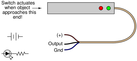
Assume the switch above is a sinking output. Show how you would connect the limit switch in the above illustration so that it makes the LED turn on when actuated, assuming the switch’s internal transistor is configured to sink current through the output lead.
{\bullet} Identify an object an inductive proximity switch would be able to detect.
{\bullet} Identify an object an optical proximity switch would be able to detect.
{\bullet} Identify an object a capacitive proximity switch would not be able to detect.
{\bullet} Identify an object an ultrasonic proximity switch would not be able to detect.Reveal answer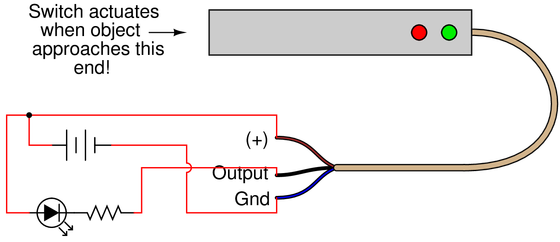
Since the output wire of the switch was declared to be sinking, the load (LED and resistor) must be externally powered, and the return path to the power supply ‘-’ goes through the switch.
If this were a sourcing switch, as many switches are, the output wire must power the positive side of the LED, with the resistor returning directly back to the power supply ‘-’.
-
Question 21
Limit switches are electrical switches designed to actuate based on the motion or position of an object, rather than the touch of a human operator. Simple limit switches rely on direct, physical contact, using a lever, sometimes tipped with a roller for low friction:

Show how you would connect the limit switch in the above illustration so that it makes the light turn off when actuated (i.e. the light will be on when no one touches the switch lever).
Reveal answer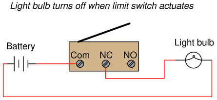
If this lamp is non-polar, the power supply ‘+’ may be connected to either the lamp or to the limit switch with success.
The example diagram above shows ‘ground side switching’ where the switch lies between the load and ground. For more detail, read the technical article on this topic.
Notes:Reference article links: