 Facebook
 Google
 GitHub
 Linkedin
Electricity and Electronics
DC Circuit Calculations
-
Question 1
Calculate the amount of voltage between points A and B in this circuit. You must sketch polarity marks (+ , -) on the schematic diagram to show the polarity of $V_{AB}$, as well as show all of your mathematical work!
 Reveal answer
Key Application for this Solution: Ohm’s Law
$V_{AB}$ = 9.198 volts, A being the higher voltage point than B.
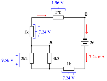
The voltage between points A and B is the supply voltage (26 volts) minus the voltage drops across the 1k and parallel subnetwork resistors. Alternatively, one could calculate $V_{AB}$ by adding the voltage drops of the 1k and 270 ohm resistors.
The latter solution makes it easiest to see the polarity of $V_{AB}$: noting how the voltage drops across the 1k and 270 ohm resistors are additive, we see point A being the most positive and point B being the most negative.
The solution is derived by combining all resistors into one equivalent value and applying Ohm’s Law to determine the circuit current and, subsequently, the voltage drop across each resistor.
Assuming resistor numbering with the 270 $\Omega$ resistor as the 5th and final resistor:
$$R_{total}=R_1+1/(1/R_2+1/R_3)+R_4+R_5$$
$$R_{total}=3.59~k \Omega$$
$$I_{total}={26~V \over 3.59~k \Omega}$$
$$I_{total}=7.24~mA$$
$$V_{R_1}=7.24~mA \cdot 1~k \Omega$$
$$V_{R_1}=7.24~V$$
$$V_{R_{2,3}}=7.24~mA \cdot 1.32~k \Omega$$
$$V_{R_{2,3}}=9.56~V$$
$$V_{R_4}=7.24~mA \cdot 1~k \Omega$$
$$V_{R_4}=7.24~V$$
$$V_{R_5}=7.24~mA \cdot 270~ \Omega$$
$$V_{R_5}=1.96~V$$
-
Question 2
Calculate the resistance between points A and B ($R_{AB}$) for the following resistor networks:
 Reveal answer
Key Application for this Solution: Resistor Network Equivalents
Figure 1:
Two equal parallel paths, each consisting of two series 500 Ω resistors.
Two 1000 Ω resistors in parallel equals 500 Ω.
$R_{AB}$ = 500 Ω
Figure 2:
One 1000 Ω resistor in parallel with three equal series resistors (3000 Ω total).
1000 Ω in parallel with 3000 Ω equals 750 Ω.
$R_{AB}$ = 750 Ω
Figure 3:
This is a series of two parallel networks. The first network has a 2000 Ω and a 5000 Ω in parallel (1429 Ω). The second network has a 100 Ω and a 470 Ω in parallel (82 Ω).
$R_{AB}$ = 1429 Ω + 82 Ω.
$R_{AB}$ = 1.511 kΩ
Figure 4:
A bit of a ‘trick’ problem. After the current passes through the 940 Ω resistor, it may pass unresisted to point B. Therefore, the 470 Ω and 250 Ω resistors are not factored into the equation.
In other words, those two latter resistors have been ‘shorted’ out of the equation, and all resistance in that path is now in parallel with a ‘nearly 0 Ω resistor’. According to the parallel circuit equation, when one parallel resistor is nearly zero, the equivalent network resistance is also nearly zero.
$R_{AB}$ = 940 Ω
Figure 5:
Three parallel networks, from left to right, include one 2.2 kΩ, a second 2.2 kΩ, and then a series consisting of two 2.2 kΩ, for a 4.4 kΩ equivalent.
A parallel network of 2.2 kΩ, 2.2 kΩ, and 4.4 kΩ equals 880 Ω.
$R_{AB}$ = 880 Ω
Figure 6:
This circuit can be difficult to visualize without mentally or physically redrawing the resistor arrangement.
Between A and B lie a 100 Ω resistor, this is plain. But in addition, there lies a second path with a 220 Ω resistor followed by parallel branches of 470 Ω and 330 Ω, either of which presents possible paths to B.
The equivalent resistance, then, is found by:
470 Ω and 330 Ω in parallel = 194 Ω
This is in series with (added to) 220 Ω to = 414 Ω
This 414 Ω is in parallel with 100 Ω to = 80.5 Ω
$R_{AB}$ = 80.5 Ω
Notes:Discuss with your students how they approached each of these problems, and let the entire class participate in the reasoning process. The point of this question, like most of the questions in the Socratic Electronics project, is not merely to obtain the correct answers, but to stimulate understanding of {\it how} to solve problems such as these.
-
Question 3
Use Kirchhoff’s Voltage Law to calculate the magnitude and polarity of the voltage across resistors $R_2$ and $R_4$ in this resistor network:
 Reveal answer
Key Application for this Solution: Kirchhoff’s Voltage Law (KVL)
“The Sum of All Voltage Drops in a Closed Loop Equal 0”
This can be rephrased to state that all increases in voltage must be equal to drops in voltage in any closed loop.
For the loop on the left, this is simple:
$$V_{source} = V_{R1}+V_{R3}+V_{R2}$$
$$17~V=10~V+4~V+V_{R2}$$
$$V_{R2} = 3~V$$
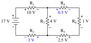
But for the loop on the right, with no source voltage, the polarity of each resistor must be carefully observed, and the true purpose of Kirchhoff’s Law is revealed.
If a loop is drawn in a clockwise manner around the right-side closed loop, $R_4$, $R_6$, and $R_5$ are a positive drop in voltage (going from + to -), but $R_3$ is actually an increase, or a negative drop (- to +).
Therefore, we return to Kirchhoff’s Law in its true form, and add all of these drops to equal 0:
$$V_{R4}+V_{R6}+V_{R5}-V_{R3}=0$$
$$V_{R4}+1+2.5-4=0$$
$$V_{R4}-0.5=0$$
$$V_{R4}=0.5$$
Notes:In your discussion, be sure to explore more than one “loop” when using KVL. Not only does this demonstrate the arbitrary nature of your loop choice, but it also serves as a double-check for your work!
It is not necessary to know anything about series-parallel or even parallel circuits in order to solve for R_2’s or R_4’s voltage—all one needs to know is how to use Kirchhoff’s Voltage Law.
-
Question 4
Imagine you are using a digital voltmeter to measure voltages between pairs of points in a circuit, following the sequence of steps shown in the following diagrams:
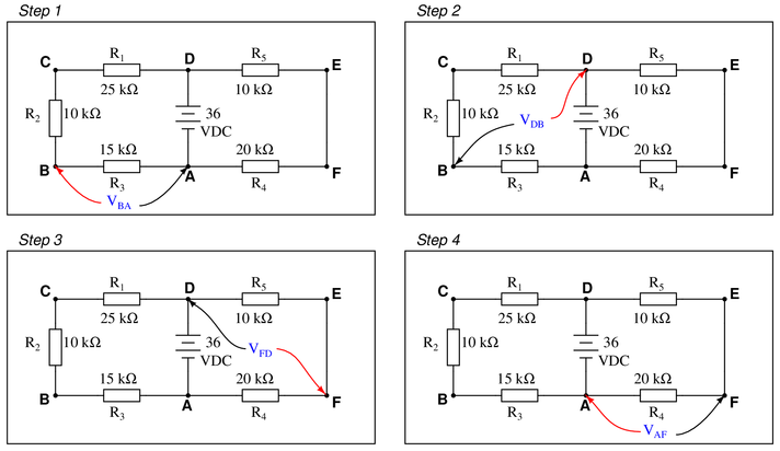
How much voltage would be registered by the voltmeter in each of the steps? Be sure to include the sign of the DC voltage measured (note the coloring of the voltmeter leads, with the red lead always on the first point denoted in the subscript: $V_{BA}$ = red lead on “B” and black lead on “A”):
{\bullet} $V_{BA} = $
{\bullet} $V_{DB} = $
{\bullet} $V_{FD} = $
{\bullet} $V_{AF} = $What is the algebraic sum of these voltages?
Reveal answerKey Application for this Solution: Voltage Divider Equation
In each step, the voltage divider equation can be a very useful tool:
Step 1:
In loop DCBAD, there is a supply of 36 volts, being dropped across an equivalent 50 kΩ. As the measurement terminals BA are across the 15 kΩ resistor, the ratio of 15 k : 50 k = 0.3, or 30% of the voltage. 36 volts multiplied by 0.3 = 10.8 volts.
Formally, this would appear as follows:
$$V_{R3}=V_{source} \times{R_3 \over R_{loop~total}}$$
$$V_{R3}=36~V \times{15~k \Omega \over 50~k \Omega}$$
{\bullet} $V_{BA} = +10.8$ volts
Step 2:
The process is the same, except we are no longer interested in $V_{R3}$ but rather the voltage across both $R_1$ and $R_2$ which are in series. Therefore, simply replace $R_3$ in the previously used formula with $R_1+R_2$ and the voltage will be found.
{\bullet} $V_{DB} = +25.2$ voltsAlternatively, since you have already found $V_{R3}$, it can simply be subtracted from the source voltage to arrive at the same conclusion (remember Kirchhoff’s Voltage Law?)
Step 3:
In loop DEFAD, there are only two resistors, so the total resistance of this loop is 30 kΩ. To determine $V_{R5}$, we use a similar voltage divider equation:
$$V_{R5}=V_{source} \times{R_5 \over R_{loop~total}}$$
$$V_{R5}=36~V \times{10~k \Omega \over 30~k \Omega}$$
The only difference between this step and previous steps is the alignment of the measurement leads. The Positive lead (red) is at a lower voltage potential than the negative (black) lead. This means that voltage will, in magnitude, be according to our equation, but the polarity will be negative.
{\bullet} $V_{FD} = -12.0$ voltsStep 4:
At this point, the method of calculating $V_{AF}$ should be quite clear, but once again, the positive lead of the meter is at a lower voltage than the negative lead, so the measurement polarity will be negative once again.
{\bullet} $V_{AF} = -24.0$ volts
Notes:Ask yourself this question: “Will the algebraic sum of voltage measurements ever be other than zero in a loop?’’
-
Question 5
Calculate the amount of voltage dropped across resistor $R_2$:

Also, note the direction of current through it and the polarity of the voltage drop across it.
Reveal answerKey Application for this Solution: Ohm’s Law
Although the voltage divider equation can easily be employed as in the previous exercise, let us use Ohm’s Law to provide the voltage for each component.
First, calculate the equivalent total resistance of the circuit to determine current:
$$R_{total}=R_1+{1 \over {1 \over R_2}+{1 \over R_3}}$$
$$R_{total}=1500+{1 \over {1 \over 2200}+{1 \over 5000}}$$
$$R_{total}=3027 \Omega~or~3.027~k\Omega$$
Now, calculate the total current in the circuit using Ohm’s law:
$$I_{total}={V_{source} \over R_{total}}$$
$$I_{total}={24~V \over 3.027~k\Omega}$$
$$I_{total}=7.93~mA$$
The voltage drop of $R_1$ is simple $V=I \cdot R$ since the entire total current passes through $R_1$
$$V_{R1} =11.89~volts$$
Now, the voltage across both $R_2$ and $R_3$ is the remaining voltage following this drop.
$$V_{R2,3}=24~V-11.89~V$$
$$V_{R2,3}=12.11~V$$
So, $V_{R2} = 12.11~V$, positive on top and negative on bottom. If you follow conventional flow notation, this means current goes down through resistor $R_2$. The actual flow of electrons through $R_2$, however, is up.
Notes:Discuss with your students how they obtained their answers for this question. The reasoning and procedures are far more important than the actual answer itself.
Students often have difficulty formulating a method of solution: determining what steps to take to get from the given conditions to a final answer. While it is helpful at first for you (the instructor) to show them, it is bad for you to show them too often, lest they stop thinking for themselves and merely follow your lead. A teaching technique I have found very helpful is to have students come up to the board (alone or in teams) in front of class to write their problem-solving strategies for all the others to see. They don’t have to actually do the math, but rather outline the steps they would take, in the order they would take them.
-
Question 6
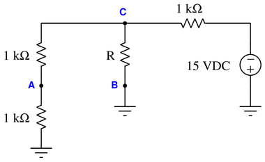
Complete the table of values for this circuit:
 Reveal answer
Key Applications for this Solution: Ohm’s Law and Combinational Circuit Analysis
By this time, the use of Ohm’s Law should be getting more familiar, so instead of outlining each formula exactly, the order of steps will be shown, and you can match your answers to the completed table below. If, at any point, your answers do not match, you can stop and check your work at that point.

Step 1: Insert the total voltage into the table: 15 V
Step 2: Calculate the total resistance (the parallel combination of $R_2$ and $R_3$, which is now in series with $R_1$)
Step 3: Total voltage and resistance provide the total current (Ohm’s Law)
Step 4: The total current equals the current in $R_1$ since there is no alternate path. Insert that value into the table.
Step 5: With the knowledge of $I_{R_1}$, you can calculate the voltage drop of $R_1$ (Ohm’s Law)
Step 6: The voltage drop of both $R_2$ and $R_3$ are the same, being in parallel. You can find this value by subtracting the voltage lost at $R_1$ from the total voltage.
Step 7: Knowing the voltage drop and resistance of both $R_2$ and $R_3$, the current of each can be calculated (Ohm’s Law). Note that since $R_3$ has a lower resistance, it should have a higher current.
Step 8: To find the total power and the power dissipated by each resistor, multiply each column’s voltage by its current. Regardless of arrangement - series, parallel, or combination, the sum of all components’ power should equal the total.
Notes:A noteworthy feature of this circuit’s schematic is how the power supply connections are shown. Unlike many of my schematic diagrams, I do not show a “battery” symbol here for a voltage source. Instead, I show power supply “rail” symbols (flat line and a ground symbol). Let your students know that this is very common symbolism in modern schematics, and that is merely saves having to draw lines to a voltage source symbol (as well as the source symbol itself).
Discuss with your students what a good procedure might be for calculating the unknown values in this problem, and also how they might check their work.
Students often have difficulty formulating a method of solution: determining what steps to take to get from the given conditions to a final answer. While it is helpful at first for you (the instructor) to show them, it is bad for you to show them too often, lest they stop thinking for themselves and merely follow your lead. A teaching technique I have found very helpful is to have students come up to the board (alone or in teams) in front of class to write their problem-solving strategies for all the others to see. They don’t have to actually do the math, but rather outline the steps they would take, in the order they would take them.
-
Question 7
Suppose you were designing a circuit that required two LEDs for “power on” indication. The power supply voltage is 15 volts, and each LED is rated at 1.6 volts and 20 mA. Calculate the dropping resistor sizes and power ratings:

After doing this, a co-worker looks at your circuit and suggests a modification. Why not use a single dropping resistor for both LEDs, economizing the number of components necessary?
Re-calculate the dropping resistor ratings (resistance {\it and} power) for the new design.
Reveal answerKey Application for this Solution: Ohm’s Law
Resistors employed for LED protection are quite simple to calculate.
The voltage dropped by the resistor must be the difference between the source voltage and the voltage dropped by the LED. If there are many LEDs in series, add up the voltages.
Then, the resistor value is equal to the resistor’s voltage divided by the desired current through the LED(s). This is simply Ohm’s Law at work. Again.
For Two Resistors:
$$R_{protection}={V_{source}-V_{LED} \over I_{LED}}$$
$$R_{protection}={15~V-1.6~V \over 20~mA}$$
With two resistors: $R_1 = R_2 = 670 \> \Omega$, rated for at least 0.268 watts (1/2 watt would be a practical rating).
For One Resistor:
When combined into a single resistor, the total current passed through the resistor must provide 20 mA for each LED, or a total of 40 mA. This will yield a resistor value of exactly half the previous scenario, but it will also increase the power rating.
With one resistor: $R_1 = 335 \> \Omega$, rated for at least 0.536 watts (1 watt would be a practical rating).
Note: It is not recommended to use a single resistor for multiple parallel LEDs unless it is guaranteed that both LEDs will have the same voltage drop. If the voltage ratings differ, only the LED with the lower rating will successfully illuminate, leading to an assumption of faulty components. If the LEDs are different colors, it is almost certain that you must use individual protection resistors.
A Third Option:
Since the LEDs only require 1.6 volts each, and the 15 volt source is more than enough to supply both of the LEDs, we can easily place them in series.
This scenario would reduce the voltage dropped by the single resistor, and would subsequently require a lower power resistor. Since the LEDs are in series, the current remains at 20 mA.
$$R_{protection}={V_{source}-V_{LED1}-V_{LED2} \over I_{LED}}$$
$$R_{protection}={15~V-1.6~V-1.6~V \over 20~mA}$$
With one resistor: $R_1 = 590 \> \Omega$, rated for at least 0.236 watts (now, a 1/4 watt would be a practical rating).
A benefit of this option is that we can increase the number of series LEDs, even if the voltages (colors) are different, and the protection resistor will be minimized.
A disadvantage is that all of those series LEDs must handle the same current.
Notes:If students are not yet familiar with the ``+V’’ symbol used to denote the positive power supply connection in this schematic, let them know that this is a very common practice in electronic notation, just as it is common to use the ground symbol as a power supply connection symbol.
The follow-up question is a very practical one, for it is seldom that you have the exact components on-hand to match the requirements of a circuit you are building. It is important to understand which way is safer to err (too large or too small) when doing ``as-built’’ design work.
-
Question 8
Complete the table of values for this circuit:
 Reveal answer
Key Applications for this Solution: Ohm’s Law and Combinational Circuit Analysis
This circuit should be very reminiscent of the procedure used in Question 6 above.
Sometimes, the use of a voltage supply on the right side of the circuit is unusual and can be confusing. If it helps, re-write the circuit as if looking in a mirror, but be sure to preserve the resistor names and values in this mirror image.

Step 1: Insert the total voltage into the table: 12 V
Step 2: Calculate the total resistance (the parallel combination of $R_1$ and $R_2$, which is now in series with $R_3$)
Step 3: Total voltage and resistance provide the total current (Ohm’s Law)
Step 4: The total current equals the current in $R_3$ since there is no alternate path. Insert that value into the table.
Step 5: With the knowledge of $I_{R_3}$, you can calculate the voltage drop of $R_3$ (Ohm’s Law)
Step 6: The voltage drop of both $R_1$ and $R_2$ are the same, being in parallel. You can find this value by subtracting the voltage lost at $R_3$ from the total voltage.
Step 7: Knowing the voltage drop and resistance of both $R_1$ and $R_2$, the current of each can be calculated (Ohm’s Law). Note that since $R_2$ has a lower resistance, it should have a higher current.
Step 8: To find the total power and the power dissipated by each resistor, multiply each column’s voltage by its current. Regardless of arrangement - series, parallel, or combination, the sum of all components’ power should equal the total.
-
Question 9
Complete the table of values for this circuit:
 Reveal answer
Key Applications for this Solution: Ohm’s Law and Combinational Circuit Analysis
This circuit is much like the previous, but with additional resistors come extra steps.

Step 1: Insert the total voltage into the table: 18 V
Step 2: Calculate the total resistance:
Step 2a: First, $R_1$ and $R_2$ are combined in series
Step 2b: This series is now combined in parallel with $R_3$
Step 2c: This new parallel is now combined in series with $R_4$ and $R_5$
Step 3: Total voltage and resistance provide the total current (Ohm’s Law)
Step 4: The total current equals the current in both $R_4$ and $R_5$ since there is no alternate path to and from the source, except through these resistors. Insert that value into the table for both resistors.
Step 5: With the knowledge of $I_{R_4,5}$, you can calculate the voltage drop of $R_4$ and $R_5$ (Ohm’s Law)
Step 6: The voltage drop of $R_3$ will be the next objective. You can find this value by subtracting the voltage lost at $R_4$ and $R_5$ from the total voltage.
Step 7: Knowing the voltage drop and resistance of $R_3$, the current $I_3$ can be calculated (Ohm’s Law).
Step 8: The current through $R_1$ and $R_2$ can now be found as the as the difference between the total current, and the current diverted through $R_3$. Subtract $I_{total}-I_3$
Step 9: The voltage drop of $R_1$ and $R_2$ can now be found by multiplying $I_{1,2}$ by $R_1$ and $I_{1,2}$ by $R_2$.
Step 8: To find the total power and the power dissipated by each resistor, multiply each column’s voltage by its current. Once again, regardless of arrangement, the sum of all components’ power should equal the total.
Notes:Discuss with your students what a good procedure might be for calculating the unknown values in this problem, and also how they might check their work.
-
Question 10
Complete the table of values for this circuit:
 Reveal answer
Key Applications for this Solution: Ohm’s Law and Combinational Circuit Analysis
This is another example of a circuit that appears confusing because of the unusual arrangement of the middle diagonal line, and the power supply in the center of the circuit.
First, make the line vertical instead of diagonal.
Then, swap places: switch $R_1$ with the voltage source and $R_2$.
Now, the voltage source and $R_2$ are on the far left side, and $R_1$ has moved to the middle.
Once this is done, the circuit will most likely feel much less intimidating.

Step 1: Insert the total voltage into the table: 11 V
Step 2: Calculate the total resistance:
Step 2a: $R_3$ and $R_4$ added in series
Step 2b: This value is in parallel with $R_1$
Step 2b: This value is in series with $R_2$ (notice how $R_2$ is the only resistor that all current must travel through)
Step 3: Total voltage and resistance provide the total current (Ohm’s Law)
Step 4: The total current equals the current in $R_2$ since there is no alternate path. Insert that value into the table.
Step 5: With the knowledge of $I_{R_2}$, you can calculate the voltage drop of $R_2$ (Ohm’s Law)
Step 6: The voltage drop of $R_1$ will be the next objective. You can find this value by subtracting the voltage lost at $R_2$ from the total voltage.
Step 7: Knowing the voltage drop and resistance of $R_1$, the current $I_1$ can be calculated (Ohm’s Law).
Step 8: The current through $R_3$ and $R_4$ can now be found as the as the difference between the total current, and the current diverted through $R_1$. Subtract $I_{total}-I_1$
Step 9: The voltage drop of $R_3$ and $R_3$ can now be found by multiplying $I_{3,4}$ by $R_3$ and $I_{3,4}$ by $R_4$.
Step 10: To find the total power and the power dissipated by each resistor, multiply each column’s voltage by its current. Regardless of arrangement - series, parallel, or combination, the sum of all components’ power should equal the total.
Notes:Discuss with your students what a good procedure might be for calculating the unknown values in this problem, and also how they might check their work.
Students often have difficulty formulating a method of solution: determining what steps to take to get from the given conditions to a final answer. While it is helpful at first for you (the instructor) to show them, it is bad for you to show them too often, lest they stop thinking for themselves and merely follow your lead. A teaching technique I have found very helpful is to have students come up to the board (alone or in teams) in front of class to write their problem-solving strategies for all the others to see. They don’t have to actually do the math, but rather outline the steps they would take, in the order they would take them.
-
Question 11
Identify which of these components are connected directly in series with each other, and which are connected directly in parallel with each other:

Assume that the open wire ends are connection points to a power source. In circuits where ground symbols appear, consider ground as the other side of the power source.
Reveal answerKey Application for this Solution: Resistor Networks
Figure 1:
R1 in series with SW1.
Figure 2:
R1 in series with R2; R3 in parallel with R4.
Figure 3:
R1 parallel with R2.
Figure 4:
R1 parallel with R2.
Figure 5:
L1 in series with C1.
Figure 6:
R3 in parallel with R4.
Notes:Work with your students to clearly identify rules by which series and parallel connections may be identified. This is extremely important for students to grasp if they are to be successful analyzing series-parallel networks of any kind. The most common problems I encounter as an electronics instructor with reference to series-parallel are invariably related to students’ lack of ability to consistently distinguish series sub-networks and parallel sub-networks in series-parallel combination circuits.
-
Question 12
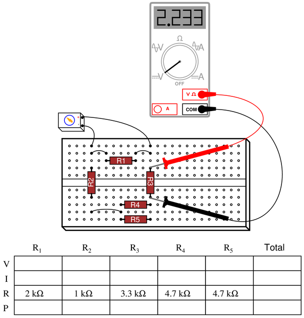
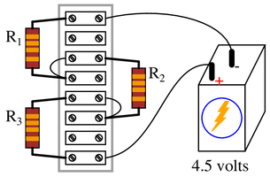
Complete the table of values for this circuit:
 Reveal answer
Key Applications for this Solution: Ohm’s Law and Combinational Circuit Analysis
First, visualization can be a challenge in this circuit. Try turning the entire breadboard 90$^o$ counter-clockwise, and you might be surprised at how familiar it suddenly becomes!
As an additional note, DO NOT assume the battery to be 9 volts just because it looks like a 9 volt battery. We must determine the source voltage using the measured value on the meter.

Step 1: Record the measured voltage for $R_3$ in the table.
Step 2: Using this voltage value, calculate $I_3$ using Ohm’s Law.
Step 3: This same current must be going through $R_4$ and $R_5$, as they are in series with $R_3$. Fortunately, they are equally-sized resistors, so both $R_4$ and $R_5$ will have half the current of $R_3$.
Step 4: Using Ohm’s Law, you can now calculate the voltage dropped by $R_4$ and $R_5$. They should be equal, considering they are in parallel with each other.
Step 5: Moving on to $R_2$, the current in this resistor is equal to the current in $R_3$ which we found earlier. Note how the current split between $R_4$ and $R_5$ re-combines again to go through $R_2$.
Step 6: With the current now known in $R_2$, you can calculate the voltage dropped by $R_2$ using Ohm’s Law.
Step 7: The added voltage of $R_3$, $R_{4,5}$, and $R_2$ is equal to the source voltage (drawing a loop around the outside circuit should reveal this by applying Kirchhoff’s Voltage Law)
Step 8: That source voltage is also equal to the voltage dropped by $R_1$. Once again, Kirchoff’s Voltage Law may prove this.
Step 9: The current in $R_1$ can now be calculated by using Ohm’s Law.
Step 10: The total source current is found by adding the current in $R_1$ + the current in $R_3$ since these resistors represent the two branches of the circuits.
Step 11: The total resistance of the circuit is found by using Ohm’s Law $R_{total} = {V_{total} \over I_{total}}$
Step 10: To find the total power and the power dissipated by each resistor, multiply each column’s voltage by its current. Regardless of arrangement - series, parallel, or combination, the sum of all components’ power should equal the total.
Notes:Ask your students to identify components in this series-parallel circuit that are guaranteed to share the same voltage, and components that are guaranteed to share the same current, without reference to any calculations. This is a good exercise in identifying parallel and series interconnections, respectively.
Students often have difficulty formulating a method of solution: determining what steps to take to get from the given conditions to a final answer. While it is helpful at first for you (the instructor) to show them, it is bad for you to show them too often, lest they stop thinking for themselves and merely follow your lead. A teaching technique I have found very helpful is to have students come up to the board (alone or in teams) in front of class to write their problem-solving strategies for all the others to see. They don’t have to actually do the math, but rather outline the steps they would take, in the order they would take them.
-
Question 13
When the 5 kΩ potentiometer in this circuit is set to its 0% point, the output voltage is zero.

Calculate what the output voltages will be if a 1 kΩ load resistor is connected between the “$V_{out}$” terminal and ground for each of the following adjustments:
{\bullet} At 0%
{\bullet} At 25%
{\bullet} At 50%
{\bullet} At 75%
{\bullet} At 100%Reveal answerKey Application for this Solution: Variable Voltage Dividers
At 0%, the output voltage will be 0.
At 25%, 1.25 kΩ of the total 5 kΩ are in parallel with the 1 kΩ load. This leaves 3.75 kΩ before the $V_{out}$ terminal. The total resistance is 3.75 kΩ + (parallel of 1.25 kΩ and 1 kΩ), which equals 4305.5 Ω.The output resistance in question will now be the parallel of that 1.25 kΩ and 1 kΩ load (555.5 Ω)
Using the voltage divider equation:
$$V_{out}=10~V{R_{output} \over R_{total}}$$
$$V_{out}=10~V{555.5 \Omega \over 4305.5 \Omega}$$
$$V_{out}=1.29~V$$
At 50%, The total resistance is now 2.5 kΩ + (parallel of 2.5 kΩ and 1 kΩ. The output resistance is just the final part, the parallel of 2.5 kΩ and 1 kΩ.
$$V_{out}=10~V{714.3 \Omega \over 3214.3 \Omega}$$
$$V_{out}=2.22~V$$
At 75%, The total resistance is now 1.25 kΩ + (parallel of 3.75 kΩ and 1 kΩ. The output resistance is just the final part, the parallel of 3.75 kΩ and 1 kΩ.
$$V_{out}=10~V{789.5 \Omega \over 2039.5 \Omega}$$
$$V_{out}=3.87~V$$
At 100%, The total resistance is now entirely in the load, therefore, the entire source voltage is dropped across the load.
$$V_{out}=10.0~V$$
An examination of these numbers shows that as the value of the potentiometer is incremented by 25% each time, the change in output is far from consistent. The change in output between 0%-25% is only 1.29 volts, yet the difference in output between 75%-100% is 6.13 volts!
When practical loads are placed onto circuits, the changes in output are no longer linear.
Notes:This question is really nothing more than five loaded voltage divider problems packed into one! It is a very practical question, as potentiometers are very often used as variable voltage dividers, and students must realize the effects a load resistance will have on the characteristics of such dividers. Point out to them the extreme nonlinearity created by the inclusion of the load resistance.
-
Question 14
Determine the voltages (with respect to ground) at points A and B in this circuit under four different conditions: both loads off, load 1 on (only), load 2 on (only), and both loads on:

Voltage Both loads off Load 1 on (only) Load 2 on (only) Both loads on $V_A$ $V_B$ Reveal answerKey Applications for this Solution: Ohm’s Law and Combinational Circuit Analysis
Voltage Both loads off Load 1 on (only) Load 2 on (only) Both loads on $V_A$ 26.4 V 26.3 V 22.4 V 22.3 V $V_B$ 5 V 4.46 V 4.23 V 3.78 V Notes:Students will have to re-consider (and possible re-draw) the circuit for each loading condition, which is one of the major points of this question. The fact that a circuit can ``change’’ just by throwing a switch is an important concept for electronics students to grasp.
Another concept employed in this question is that of voltages specified at single points with an implied reference of ground. Note to students how each voltage was simply referenced by a single letter, either {\bf A} or {\bf B}. Of course there is no such thing as voltage at a single point in any circuit, so we need another point to reference, and that point is ground. This is {\it very} commonly seen in electronic circuits of all types, and is a good thing to be exposed to early on in one’s electronics education.
A much less obvious point of this question is to subtly introduce the concept of discrete states (loading conditions) available with a given number of boolean elements (switches). Given two load switches, there are four possible states of circuit loading, previewing binary states in digital circuits.
-
Question 15
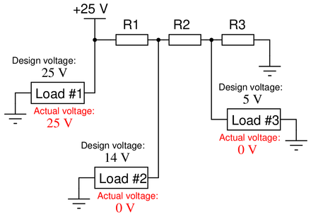
One of the resistors in this voltage divider circuit is failed open. Based on the voltage readings shown at each load, determine which one it is:
 Reveal answer
Key Application for this Solution: Resistor Failure Analysis
Resistor R1 has failed open. This is evident because only load #1 is receiving any power; the other two loads are completely “dead”.
If resistor R2 had failed open, then load #2 would be receiving power through R1, and only R3 would exhibit 0 volts.
Finally, if R3 was failed open, all loads would receive power, but the voltage on loads #2 and #3 would be higher than expected (the presence of R3 creates a parallel circuit, lowering the resistance, and therefore the voltage, at the end of the circuit).
Notes:Discuss with your students how they were able to predict R1 was the faulty resistor. Is there any particular clue in the diagram indicating R1 as the obvious problem?
-
Question 16
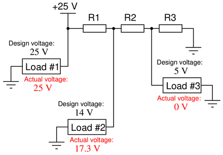
One of the resistors in this voltage divider circuit is failed open. Based on the voltage readings shown at each load, determine which one it is:
 Reveal answer
Key Application for this Solution: Resistor Failure Analysis
Resistor R2 has failed open. We can tell this because load #3 is receiving no power at all while load #2 is being over-powered.
A good question to pose to yourself: Why does the voltage of load #1 remain at 25 volts in both this question and the previous, when both circuits have faulty components? Why do the other loads change, but not load #1?
Notes:Discuss with your students how they were able to predict R2 was the faulty resistor. Is there any particular clue in the diagram indicating R2 as the obvious problem?
-
Question 17
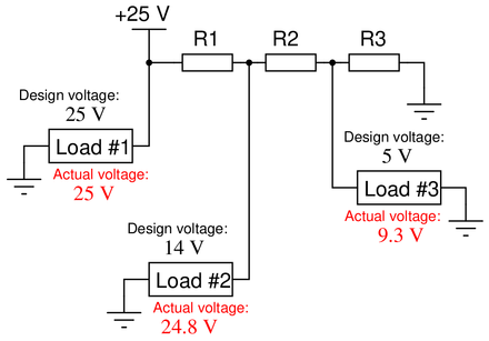
One of the resistors in this voltage divider circuit is failed (either open or shorted). Based on the voltage readings shown at each load, determine which one and what type of failure it is:
 Reveal answer
Key Application for this Solution: Resistor Failure Analysis
Resistor R1 has failed (partially) shorted. We can tell this because both loads #2 and #3 are being over-powered.
If R1 had shorted entirely, the voltage of load #2 and load #1 would be equal, since there would be no resistor to change the voltage between them.
If R2 had shorted, the voltage of loads #2 and #3 would be equal (or very nearly equal).
If R1 had shorted, the voltage of load #3 would be zero, since both sides of load #3 would, essentially, be connected to ground.
Notes:Discuss with your students how they were able to predict R1 was the faulty resistor. Is there any particular clue in the diagram indicating R1 as the obvious problem? Some students may suspect an open failure in resistor R3 could cause the same effects, but there is a definite way to tell that the problem can {\it only} come from a short in R1 (hint: analyze resistor R2).
Explain that not all ``shorted’’ failures are ``hard’’ in the sense of being direct metal-to-metal wire connections. Quite often, components will fail shorted in a ``softer’’ sense, meaning they still have some non-trivial amount of electrical resistance.
-
Question 18
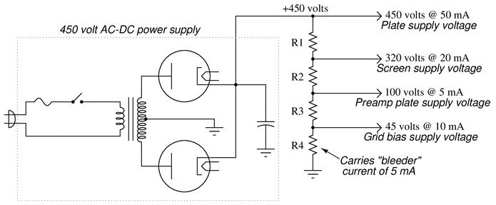
Old vacuum-tube based electronic circuits often required several different voltage levels for proper operation. An easy way to obtain these different power supply voltages was to take a single, high-voltage power supply circuit and “divide” the total voltage into smaller divisions.
These voltage divider circuits also made provision for a small amount of “wasted” current through the divider called a bleeder current, designed to discharge the high voltage output of the power supply quickly when it was turned off.
Design a high-voltage divider to provide the following loads with their necessary voltages, plus a “bleeder” current of 5 mA (the amount of current going through resistor R4):
 Reveal answer
Key Applications for this Solution: Loaded Voltage Divider Analysis
The key to calculating all resistor values is to determine how much voltage each one must drop and how much current each one must carry. The current question may be answered by applying Kirchhoff’s Current Law (KCL) to each of the nodes in the circuit, while the voltage question may be answered by calculating the voltage difference between each pair of supply lines to the tube circuit.
We start with $R_4$, since we know the that must be dropped, and we know the current that must be carried.
$$R_4={45~V \over 5~mA}$$
{\bullet} $R_4 = 9~k\Omega$
Next, we can examine the node supplying the grid bias voltage. 10 mA supplies the grid bias and 5 mA is the bleeder current. This means that a total of 15 mA must be going through $R_3$. Since the voltage difference is $100~V - 45~V = 55~V$, use Ohm’s law:
$$R_3={55~V \over 15~mA}$$
{\bullet} $R_3 = 3.67~k\Omega$
Use the same process to evaluate $R_2$, with a difference of $320~V - 100~V = 220~V$ and a sum of all currents downstream: $5~mA + 15~mA = 20~mA$
$$R_3={220~V \over 20~mA}$$
{\bullet} $R_2 = 11~k\Omega$
Finally, use the same process to determine $R_1$: $450~V - 320~V = 130~V$ and $20~mA + 20~mA = 40~mA$
{\bullet} $R_1 = 3.25~k\Omega$
Notice how in this circuit, the load current is provided. This means that we cannot evaluate this circuit like a simple voltage divider, even though it may appear to look like one. The load currents indicate that this is actually a complicated series-parallel combination with many loads. Since the load current and voltages are given, we are not bogged down with the necessity to factor in these load resistances.
However, if this were calculated using voltage divider equations with loads disregarded, the values would be incorrect.
Notes:Be sure to ask your students {\it how} they obtained the solution to this problem. If no one was able to arrive at a solution, then present the following technique: simplify the problem (fewer resistors, perhaps) until the solution is obvious, then apply the same strategy you used to solve the obvious problem to the more complex versions of the problem, until you have solved the original problem in all its complexity.
-
Question 19
Calculate the necessary value of $R$ to create a voltage drop of 4 volts between test points A and B:
 Reveal answer
Key Applications for this Solution: Ohm’s Law and Combinational Circuit Analysis
This circuit is an exercise in logic.
Iv $V_{AB}$ is to be 4 volts, and point B is ground (0 volts), then point A must be 4 volts. Since point A is surrounded by two equal sized resistors in series, their voltage drop must be the same, and therefore both must be dropping 4 volts.
This leads to the conclusion that point C must be $4~V+4~V=8~V$. At this point, we know that our unknown resistor has a voltage drop of $V_R=8~V$.
Now we need to determine the current through $R$.
Since point C is 8 volts, and the source is 15 volts, the 1 kΩ beside the source must be dropping the remaining 7 volts. Therefore, the current through this resistor (in other words, the source current) will be $I_{total}={7~V \over 1~k\Omega}$ or 7 mA.
The original 1 kΩ resistors on the left side are dropping 4 volts each, and in series, their current is 4 mA (use Ohm’s Law to verify).
The current through $R$ can be found with Kirchhoff’s Current Law at point C. $7~mA-4~mA-I_R=0$
So the current through the unknown resistor $I_R=3~mA$.
$$R={V_R \over I_R}$$
$$R={8~V \over 3~mA}$$
$$R = 2.667~k\Omega$$
-
Question 20
In a parallel circuit, certain general principles may be stated with regard to quantities of voltage, current, resistance, and power. Complete these sentences, each one describing a fundamental principle of parallel circuits:
“In a parallel circuit, voltage . . .”
“In a parallel circuit, current . . .”
“In a parallel circuit, resistance . . .”
“In a parallel circuit, power . . .”
For each of these rules, explain why it is true.
Reveal answerKey Application for this Solution: Understanding Parallel Circuits
“In a parallel circuit, voltage is equal across all components.”
This is true because a parallel circuit by definition is one where the constituent components all share the same two equipotential points.
“In a parallel circuit, currents add to equal the total.”
This is an expression of Kirchhoff’s Current Law (KCL), whereby the algebraic sum of all currents entering and exiting a node must be equal to zero.
“In a parallel circuit, resistance decreases to equal the total.”
Each resistance in a parallel circuit provides another path for electric current. When resistances are connected in parallel, their combined total paths provide less opposition than any single path because the current is able to split up and proportionately follow these alternative paths.
“In a parallel circuit, power dissipations add to equal the total.”
This is an expression of the Conservation of Energy, which states energy cannot be created or destroyed. Anywhere power is dissipated in any load of a circuit, that power must be accounted for back at the source, no matter how those loads might be connected to each other.
Notes:Rules of series and parallel circuits are very important for students to comprehend. However, a trend I have noticed in many students is the habit of memorizing rather than understanding these rules. Students will work hard to memorize the rules without really comprehending {\it why} the rules are true, and therefore often fail to recall or apply the rules properly.
-
Question 21
Explain, step by step, how to calculate the amount of current ($I$) that will go through each resistor in this series circuit, and also the current ($I$) supplied by the DC voltage source:
 Reveal answer
Key Applications for this Solution: Ohm’s Law and Series Circuit Analysis
First we need to identify all the relevant principles for series circuits:
{\bullet} The algebraic sum of all voltages in the circuit will be equal to zero (Kirchhoff’s Voltage Law)
{\bullet} Current is common throughout a series circuit, because there is only one path for current in the entire circuit
{\bullet} Resistances add in seriesWe know the voltage of the source and the resistance of the three loads. However, we cannot simply apply Ohm’s Law at this point because the source voltage is not impressed entirely on any one of the loads—rather the source voltage will be split up proportionately amongst the three loads in accordance with KVL. It is important to always apply Ohm’s Law in context: $V = I \cdot R$ is true only if $V$, $I$, and $R$ apply to the same component or set of components. Here, the 36 volts of the source applies to all three resistors, not to any one resistor.
However, we may apply the principle of resistances adding in series to arrive at a total resistance value for the circuit, which we may then apply to total voltage to find total current. Adding up the three resistors’ values, we get a total resistance of $R_{total} = 1500 + 10000 + 4700 = 16200$ ohms. Total circuit current is then calculated as follows:
$$I = {V \over R} = {36~V \over 16200~\Omega} = 2.22~mA$$
It is helpful to annotate all calculated values on the circuit schematic for easy reference. The reason this is helpful is because it applies a context to the calculated value. Here we will sketch arrows (in the direction of conventional flow) to document the 2.22 mA circuit current, based on the relationship between voltage and current for sources (i.e. current exits the positive pole of a source because the source is driving that current):
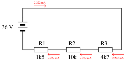
Since this is a series circuit, we know that this value of current (2.22 mA) will be common through all components. Now that we know the current through each resistor and the resistance of each resistor, we may apply Ohm’s Law to each resistor individually as such:
$$V_{R1} = I R_1 = (2.22~mA) (1500~\Omega) = 3.33~V$$
$$V_{R2} = I R_2 = (2.22~mA) (10000~\Omega) = 22.22~V$$
$$V_{R3} = I R_3 = (2.22~mA) (4700~\Omega) = 10.44~V$$
\filbreak
Once again it is recommended to annotate the circuit schematic with these calculated values, for the sake of keeping all calculations in context. The polarity (+ , -) of each voltage is important to note as well, and we know this by the relationship between voltage and current for {\it loads} (i.e. the positive pole of a load is the one where conventional flow enters, because the voltage dropped by a load is opposing current):
As a final check of our work, we may sum these three resistors’ voltage drops to ensure they do indeed add up to equal the source voltage in accordance with KVL:
$$3.33~V + 22.222V + 10.44~V = 36~V$$
-
Question 22
Determine the amount of voltage dropped by each resistor in this circuit, if each resistor has a color code of Brn, Blk, Red, Gld (assume perfectly precise resistance values—0
Also, determine the following information about this circuit:
{\bullet} Current through each resistor
{\bullet} Power dissipated by each resistor
{\bullet} Ratio of each resistor’s voltage drop to battery voltage ($E_R \over E_{bat}$)
{\bullet} Ratio of each resistor’s resistance to the total circuit resistance ($R \over R_{total}$)Reveal answerKey Application for this Solution: Series Circuit Analysis
Regardless of the resistor value, if three series resistors are placed across any voltage source, they will each drop 1/3 of the voltage. $4.5~V \div 3$.
Voltage across each resistor = 1.5 V
To determine the other properties, we must know the resistor values. Brn-Blk-Red gives us a 1.0 kΩ value. $I={V \over R}$, so $I={1.5~V \over 1.5 kΩ}$.
Current through each resistor = 1.5 mA
Power is equal to the voltage of any component multiplied by the current through that component. $P=V \cdot I$, so $P=1.5~V \cdot 1.5~mA$
Power dissipated by each resistor = 2.25 mW
In any series of resistors, the voltage ratio will equal the resistor ratio. If the resistors are equal, each resistor will drop ${1 \over n}$ the voltage, with n being the number of resistors. The resistance ratio is exactly the same calculation.
Voltage ratio = $1 \over 3$
Resistance ratio = $1 \over 3$
Notes:When performing the mathematical analysis on this circuit, there is more than one possible sequence of steps to obtaining the solutions. Different students in your class may very well have different solution sequences, and it is a good thing to have students share their differing problem-solving techniques before the whole class.
An important aspect of this question is for students to observe the identical ratios (voltage versus resistance), and determine whether or not these ratios are equal by chance or equal by necessity. Ask your students, “What kind of evidence would prove these ratios were merely equal by chance?” Setting mathematics aside and viewing this circuit from a purely experimental point of view, ask your students what data could possibly prove these ratios to be equal by chance in this particular case? Hint: it would only take a single example to prove this!
-
Question 23
Calculate the output voltages of these two voltage divider circuits ($V_A$ and $V_B$):

Now, calculate the voltage between points A (red lead) and B (black lead) ($V_{AB}$).
Reveal answerKey Applications for this Solution: Voltage Divider and Wheatstone Bridge Analysis
This circuit is really just two voltage dividers. In fact, if both resistive branches of the circuit are supplied by the same 100 V source, this would be known as a ‘Wheatstone Bridge’, a very common measurement circuit for resistive sensors.
For $V_A$, we must identify the voltage dropped by the 47 kΩ resistor with respect to the common ground. Why ground? Ground is the only consistent voltage level between the two circuits: it’s where they are connected. So if we identify first the magnitude of $V_A$, then $V_B$, the measurement is the voltage difference between them.
To first find $V_A$, we can apply the voltage divider equation:
$$V_{47~k\Omega}=100~V \cdot{47~k\Omega \over 25~k\Omega+47~k\Omega}$$
$$V_A = V_{47~k\Omega}$$
$$V_A = + 65.28~V$$
We apply the same voltage divider principle to the right side branch:
$$V_{10~k\Omega}=100~V \cdot{10~k\Omega \over 33~k\Omega+10~k\Omega}$$
$$V_B = V_{10~k\Omega}$$
$$V_B = + 23.26~V$$
Since the voltage is point A with respect to point B, we call this $V_{AB}$. This notation instructs us exactly how to set up the subtraction equation:
$$V_{AB}=V_A-V_B$$
$$V_{AB}=65.28~V-23.26~V$$
$$V_{AB} = + 42.02~V$$
The positive result tells us that point A is positive relative to point B. If the leads were reversed, the voltage would be $V_{BA}$, meaning the subtraction equation would be reversed, and the final resulting voltage would be negative. If you were to build this circuit, your measurement results would match in both magnitude and polarity.
-
Question 24
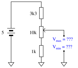
Calculate both the maximum and the minimum amount of voltage obtainable from this potentiometer circuit (as measured between the wiper and ground):
 Reveal answer
Key Application for this Solution: Variable Voltage Dividers
This adjustable min/max circuit is evaluated as two fixed circuits.
The maximum measured voltage would be exactly the same as if we measured the output across the entire 10 kΩ and the 1 kΩ in series together:
$$V_{out~max}=5~V \cdot {10~k\Omega+1~k\Omega \over 3.3~k\Omega+10~k\Omega+1~k\Omega}$$
$$V_{out~max} = 3.85~V$$
At the other extreme, the minimum voltage output will exactly as if we only measured across the 1 kΩ resistor. We can use the voltage divider equation again:
$$V_{out~min}=5~V \cdot {1~k\Omega \over 3.3~k\Omega+10~k\Omega+1~k\Omega}$$
$$V_{out~min} = 0.35~V$$
Notes:Be sure to ask your students how they obtained their answers, not just what the answers are. There is more than one correct way to analyze this circuit!
Incidentally, there is nothing significant about the use of European schematic symbols in this question. I did this simply to provide students with more exposure to this schematic convention.
-
Question 25
Suppose that an electric heater, which is nothing more than a large resistor, dissipates 500 watts of power when directly connected to a 110 volt source:

Now suppose that exact same heater is connected to one end of a long two-wire cable, which is then connected to the same 110 volt source. Assuming that each conductor within the cable has an end-to-end resistance of 3 ohms, how much power will the heater dissipate?
Reveal answerKey Application for this Solution: Series Circuit Wire Load Effects
In the first situation, we know only the power consumption of the load.
In the second situation, we are given only the resistance of the wire.
To properly analyze the change, we must be able to determine how the wire affects the load. Since we cannot calculate the power dissipation of the wires (since we know neither the resistance nor current of the load itself) we must convert the first situation to the load resistance, in order to compare the circuits in a similar fashion.
When power and voltage are known, the current can be easily calculated:
$$I={P \over V}$$
$$I={500~W \over 110~V}$$
$$I=4.54~A$$
Resistance then is:
$$R={V \over I}$$
$$R={100~V \over 4.54~A}$$
$$R_{load}=24.2~\Omega$$
We might also choose a shortcut calculation, since power directly equals the square of the voltage over the resistance. Rearranging this equation:
$$R={V^2 \over P}$$
$$R={(110~V)^2 \over 500~W}$$
$$R_{load}=24.2~\Omega$$
Knowing that the wire adds 3 Ω of resistance in each direction (to and from the source). This becomes a voltage divider equation, where we can identify the voltage dropped by the 24.2 Ω load in a circuit with a total of 30.2 Ω (the load + 6 Ω of wire).
$$V_{load}=110~V \cdot {24.2~\Omega \over 30.2~\Omega}$$
$$V_{load}=88.12~V$$
As a final step, we use the power equation from before, solving for power knowing both voltage and resistance of the heater resistor:
$$P={V^2 \over R}$$
$$P={(88.12~V)^2 \over 24.2~\Omega}$$
$$P = 320.9~W$$
Notes:The purpose of this question, besides providing a good problem-solving exercise for students, is to get them to realize one of the practical implications of power-line resistance.
-
Question 26
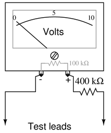
Suppose an analog voltmeter has a range of 0 to 10 volts, and an internal resistance of exactly 100 k$\Omega$:
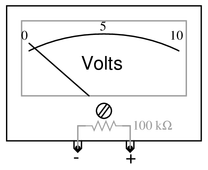
Show how a single resistor could be connected to this voltmeter to extend its range to 0 to 50 volts. Calculate the resistance of this “range” resistor, as well as its necessary power dissipation rating.
Reveal answerKey Application for this Solution: Series Circuit Voltmeter Loading
The basic problem here is how to make the voltmeter see 10 volts while it’s being connected to a source with a value of 50 volts. This will require a series resistor to drop the extra 40 volts.
We can set up similar equations (voltage ratio vs resistance ratio) and solve for the desired resistance.
$${V_{previous} \over V_{desired}}={R_{previous} \over R_{desired}}$$
$${10~V \over 50~V}={100~k\Omega \over R_{desired}}$$
$$R_{desired}=500~k\Omega$$
Since we already have 100 kΩ inside the meter, we only need to add another 400 kΩ to reach the desired target.
A power dissipation rating of ${1 \over 8}$ watt would be more than sufficient for this application. Even if all 50 volts were dropped across this one new resistor, the total power dissipation would only be:
$$P={V^2 \over R}$$$$P={(50~V)^2 \over 400~k\Omega}$$
$$P=6.25~mW$$
Even the smallest power resistor will be far more than sufficient.
Notes:Voltmeter ranging is a very practical example of voltage divider circuitry.
-
Question 27
Determine the voltages registered by a voltmeter between the following points in this circuit. Be sure to note whether the voltmeter’s indication will be a positive value or a negative value in each case:

{V_A =} (red lead on {\bf A}, black lead on ground)
{V_B =} (red lead on {\bf B}, black lead on ground)
{V_C =} (red lead on {\bf C}, black lead on ground)
{V_D =} (red lead on {\bf D}, black lead on ground)
{V_{AC} =} (red lead on {\bf A}, black lead on {\bf C})
{V_{DB} =} (red lead on {\bf D}, black lead on {\bf B})
{V_{BA} =} (red lead on {\bf B}, black lead on {\bf A})
{V_{BC} =} (red lead on {\bf B}, black lead on {\bf C})
{V_{CD} =} (red lead on {\bf C}, black lead on {\bf D})
Reveal answerKey Application for this Solution: Voltmeter Reference Voltage
In the first four examples, the voltage displayed is simply the voltage of the source. Be careful in the case of {V_D}, the positive side of the supply is grounded, therefore the measurement value is negative.
{V_A =} {\underline{ +30 volts}} (red lead on {\bf A}, black lead on ground)
{V_B =} {\underline{ +3 volts}} (red lead on {\bf B}, black lead on ground)
{V_C =} {\underline{ +9 volts}} (red lead on {\bf C}, black lead on ground)
{V_D =} {\underline{ -15 volts}} (red lead on {\bf D}, black lead on ground)
For measurements of one point with respect to another point, use the values above to form a subtraction problem: the subscript dictates the order of subtraction (first point - second point).
Providing an example for the first measurement:
$$V_{AC}=V_A-V_C$$
{V_{AC} =} {\underline{ +21 volts}} (red lead on {\bf A}, black lead on {\bf C})
Some results may be negative:
$$V_{DB}=V_D-V_B$$
$$V_{DB}=-15~V-3~V$$
{V_{DB} =} {\underline{ -18 volts}} (red lead on {\bf D}, black lead on {\bf B})
{V_{BA} =} {\underline{ -27 volts}} (red lead on {\bf B}, black lead on {\bf A})
{V_{BC} =} {\underline{ -6 volts}} (red lead on {\bf B}, black lead on {\bf C})
Subtracting a negative voltage is also perfectly valid, it simply means that the negative reference is below ground, and will result in a larger voltage difference:
$$V_{CD}=V_C-V_D$$
$$V_{CD}=9~V-(-15~V)$$
{V_{CD} =} {\underline{ +24 volts}} (red lead on {\bf C}, black lead on {\bf D})
-
Question 28
Calculate the amount of voltage between test points TP1 and TP3, and also the amount of voltage between test points TP2 and TP4:
 Reveal answer
Key Application for this Solution: Voltage Divider Equation
There are two ways to identify voltage at various points in a series circuit. The total resistance can yield total current, and Ohm’s Law instructs us to multiply each resistance by this current to obtain the voltage of each resistor.
Alternatively, since the end goal is not to measure the current, only the voltage, one might employ the voltage divider equation.
Two points that can be evaluated with no math involved are points TP1 and TP4, which are 25 V and 0 V, respectively.
Once the voltage of each resistor is known, TP3 will be equal to $V_{3.3~k\Omega~resistor}$, and TP2 will be equal to $V_{3.3~k\Omega~resistor}+V_{4.7~k\Omega~resistor}$.
$V_{TP1-TP3}$ = 15.83 volts
$V_{TP2-TP4}$ = 22.22 volts
Notes:Ask your students to explain how they obtained their answers. There is more than one correct way to answer this question!
-
Question 29
In a series circuit, certain general principles may be stated with regard to quantities of voltage, current, resistance, and power. Complete these sentences, each one describing a fundamental principle of series circuits:
“In a series circuit, voltage . . .”
“In a series circuit, current . . .”
“In a series circuit, resistance . . .”
“In a series circuit, power . . .”
For each of these rules, explain why it is true.
Reveal answerKey Application for this Solution: Series Circuit Principles
“In a series circuit, voltage drops add to equal the total.”
This is an expression of Kirchhoff’s Voltage Law (KVL), whereby the algebraic sum of all voltages in any loop must be equal to zero.
“In a series circuit, current is equal through all components.”
This is true because a series circuit by definition has only one path for current to travel. Since charge carriers must move in unison or not at all (a consequence of the Conservation of Charge, whereby electric charges cannot be created or destroyed), the current measured at any one point in a series circuit must be the same as the current measured at any other point in that same circuit, at any given time.
“In a series circuit, resistances add to equal the total.”
Each resistance in a series circuit acts to oppose electric current. When resistances are connected in series, their oppositions combine to form a greater total opposition because the same current must travel through every resistance.
“In a series circuit, power dissipations add to equal the total.”
This is an expression of the Conservation of Energy, which states energy cannot be created or destroyed. Anywhere power is dissipated in any load of a circuit, that power must be accounted for back at the source, no matter how those loads might be connected to each other.
Notes:Rules of series and parallel circuits are very important for students to comprehend. However, a trend I have noticed in many students is the habit of memorizing rather than understanding these rules. Students will work hard to memorize the rules without really comprehending why the rules are true, and therefore often fail to recall or apply the rules properly.
-
Question 30
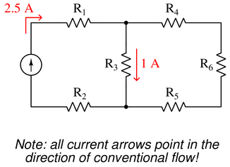
Use Kirchhoff’s Current Law to calculate the magnitude and direction of the current through resistor $R_4$ in this resistor network:
 Reveal answer
Key Application for this Solution: Kirchhoff’s Current Law
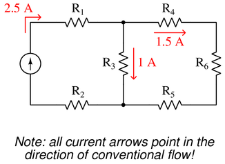
Examine the point (node) in the top-center of the circuit. Kirchoff’s Current law sates that ‘the sum of all currents entering a node equals zero’. The polarity of any point entering is positive, and anything leaving is negative.
$$I_{R_1}+I_{R_3}+I_{R_4}=0$$
$$2.5~A-1~A+I_{R_4}=0$$
$$1.5~A+I_{R_4}=0$$
$$I_{R_4}=-1.5~A$$
The negative value means that the current is exiting, not entering, through $R_4$.
 Notes:
It is not necessary to know anything about series-parallel or even parallel circuits in order to solve the $R_4$’s current—all one needs to know is how to use Kirchhoff’s Current Law.
-
Question 31
Explain, step by step, how to calculate the amount of current ($I$) that will go through each resistor in this parallel circuit, and also the current ($I$) supplied by the DC voltage source:
 Reveal answer
Key Applications for this Solution: Ohm’s Law and Parallel Circuit Analysis
First we need to identify all the relevant principles for series circuits:
{\bullet} The algebraic sum of all currents at a node will be equal to zero (Kirchhoff’s Current Law)
{\bullet} Voltage is common throughout a parallel circuit, because every component shares the same two equipotential points
{\bullet} Resistances diminish in parallelFollowing from the rule that voltage is common throughout a parallel circuit, we may conclude that each of the three resistors sees 36 volts from the source. Thus, we may immediately apply Ohm’s Law to calculate current through each of the resistors, knowing the voltage across each resistor and the resistance of each resistor:
$$I_{R1} = {V \over R_1} = {36~V \over 1500~\Omega} = 24~mA}$$
$$I_{R2} = {V \over R_2} = {36~V \over 10000~\Omega} = 3.6~mA}$$
$$I_{R3} = {V \over R_3} = {36~V \over 4700~\Omega} = 7.660~mA}$$
It is helpful to annotate all calculated values on the circuit schematic for easy reference. The reason this is helpful is because it applies a context to the calculated value. Here we will sketch arrows (in the direction of conventional flow) to document all three resistor currents, based on the relationship between voltage and current for {\it loads} (i.e. current enters the positive pole of a load because the load is opposing that current):
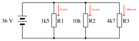
From here, we may apply KCL to calculate current values at each node, knowing that every milliamp leaving a node must be matched by a milliamp of current entering the node. Current entering the upper-right node, therefore, will be the sum of the two currents exiting that node. The same thing happens at the lower-right node, where two currents entering that node merge to form a larger current exiting:
$$I = 3.6~mA + 7.66~mA = 11.26~mA$$
Once again, we will document this calculated value on the circuit schematic to maintain its context:
Applying KCL to the upper-left and lower-left nodes, and annotating the schematic once again:
$$I = 24~mA + 11.26~mA = 35.26~mA$$
With the arrows showing this 35.26 mA current, we can see it passes straight out of (and back in to) the 36 volt source, which means this is our total current value for the parallel circuit.
-
Question 32
Calculate the total amount of current that the battery must supply to this parallel circuit:

Now, using Ohm’s Law, calculate total resistance ($R_{total}$) from total (source) voltage $V_{total}$ and total (source) current $I_{total}$.
Reveal answerKey Application for this Solution: Kirchhoff’s Current Law
Since parallel resistors each drop the same voltage, we already know the resistance and voltage of both resistors. We can easily calculate the current through each branch.
Looking at either node (top center or bottom center), we can apply Kirchoff’s Current Law to find the total circuit current.
$$I_{R_1}={10~V \over 500~\Omega$$
$$I_{R_2}={10~V \over 500~\Omega$$
Kirchoff's Current Law in bottom center node (the point of highest voltage):
$$I_{total}-I_{R_1}-I_{R_2}=0$$
$$I_{total}-20.0~mA-20.0~mA=0$
$$I_{total}-40.0~mA=0$$
$$I_{total} = 40.0~mA$$
The positive current value indeed means the current is entering the circuit node point.
In any circuit, regardless of construction, if we know the source voltage and the total current exiting and entering the source, the equivalent total resistance is found by using Ohm’s Law with these two values.
$$R_{total} = {V_{source} \over I_{total}$$
$$R_{total} = {10~V \over 40.0~mA$$
$$R_{total} = 250~\Omega$$
Notes:While some students seem able to immediately grasp the concept of parallel resistances diminishing in (total) value, it is worthwhile to approach it from an Ohm’s Law perspective as well to give other students a more formal rationale for this effect.
-
Question 33
Complete the table of values for this circuit:
 Reveal answer
Key Applications for this Solution: Ohm’s Law and Parallel Circuit Analysis
When someone understands Ohm’s Law and Watt’s Law, they can see that knowing any two values for a component allows them to calculate the other two.
This adds tremendous value to this tabular format of information. Each component and the circuit total are columns, and by looking down each column, we can find any place with 2 known values and apply the laws to calculate the other two. This is by no means cheating, since it involves an application of the same mathematical relationships, it simply allows us to locate and arrange the information in an organized fashion.

Step 1: Fill in the resistor values and the source voltage (the only known values)
Step 2: Since this is a parallel circuit, the source voltage is equal to the voltage of the resistors. Fill these voltages into the table.
Step 3: Calculate the current of each resistor since the voltage and resistance are known.
Step 4: Using Kirchoff’s Current Law (or familiarity with parallel circuits by now), the total current is the sum of all branch currents.
Step 5: The total resistance can now be calculated knowing the total voltage and current. Note: you can also find total resistance using common parallel resistance formulas, the value will be the same using either method.
Step 6: Finally, calculate total power and the power for each resistor. Once again, regardless of circuit construction, total power will always equal the sum of each component power.
Notes:Discuss with your students what a good procedure might be for calculating the unknown values in this problem, and also how they might check their work.
-
Question 34
Complete the table of values for this circuit:
 Reveal answer
Key Applications for this Solution: Ohm’s Law and Parallel Circuit Analysis
This circuit may appear confusing at first, simply because the voltage source is placed in the center. Do not be confused, this is still a normal, simple parallel circuit to be solved exactly as before.

Step 1: Fill in the resistor values and the source voltage (the only known values)
Step 2: Since this is a parallel circuit, the source voltage is equal to the voltage of all resistors. Fill these voltages into the table.
Step 3: Calculate the current of each resistor since the voltage and resistance are known.
Step 4: Using Kirchoff’s Current Law (or familiarity with parallel circuits by now), the total current is the sum of all branch currents.
Step 5: The total resistance can now be calculated knowing the total voltage and current. Note: you can also find total resistance using common parallel resistance formulas, the value will be the same using either method.
Step 6: Finally, calculate total power and the power for each resistor. Once again, regardless of circuit construction, total power will always equal the sum of each component power.
Notes:Discuss with your students what a good procedure might be for calculating the unknown values in this problem, and also how they might check their work.
-
Question 35
The circuit shown here is commonly referred to as a current divider. Calculate the voltage dropped across each resistor, the current drawn by each resistor, and the total amount of electrical resistance “seen” by the 9-volt battery:
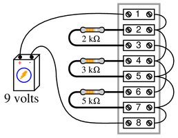
{\bullet} Voltage across each resistor =
{\bullet} Current through the 2 k$\Omega$ resistor =
{\bullet} Current through the 3 k$\Omega$ resistor =
{\bullet} Current through the 5 k$\Omega$ resistor =
{\bullet} $R_{total}$ =Reveal answerKey Applications for this Solution: Ohm’s Law and Parallel Circuit Analysis
On careful examination, this is a parallel circuit, with a similar voltage across all resistors. Being a pure parallel circuit, the source voltage of 9 volts is dropped across every resistor:
{\bullet} Voltage across each resistor = 9 volts
Knowing the voltage and resistance of each component, calculate the current:
{\bullet} Current through the 2 k$\Omega$ resistor = 4.5 mA
{\bullet} Current through the 3 k$\Omega$ resistor = 3 mA
{\bullet} Current through the 5 k$\Omega$ resistor = 1.8 mAFinally, add up the branch currents to find total current, then use the total voltage to calculate the total resistance.
{\bullet} $R_{total}$ = 967.74 $\Omega$Bonus points: If a pictorial circuit diagram is confusing, trace the wire connections and re-draw this circuit as a parallel circuit schematic. In fact, it is a very useful skill to be able to translate between schematics and literal circuits.
Notes:Some students may find the diagram hard to follow, and so they will find the task of analysis helped by drawing an equivalent schematic diagram for this circuit, with all terminal points labeled. I recommend you not suggest this solution immediately, but rather challenge your students to think of problem-solving techniques on their own. Surely, someone in the class will have thought of doing this, and the impact of such a suggestion coming from a peer is greater than if it came from you, the instructor.
Be sure to ask your students this question: ``Why is this type of circuit commonly called a {\it current divider}?’‘
-
Question 36
Examine these two variable-resistance (rheostat) networks, each one with a large-range potentiometer and a small-range potentiometer:

For each network, determine which pot is the coarse adjustment and which pot is the fine adjustment for total network resistance, and explain your reasoning.
Reveal answerKey Application for this Solution: Adjustable Current and Voltage
Series network
In a series circuit, voltage is directly proportional to resistance, therefore, the largest resistor will create the largest effect in the circuit.
100k = Coarse adjustment ; 5k = Fine adjustment
Parallel network
In a parallel circuit, current is inversely proportional to resistance, the smallest resistor will cause the greatest effect in current.
5k = Coarse adjustment ; 100k = Fine adjustment
-
Question 37
Identify which of these components are connected directly in series with each other, and which are connected directly in parallel with each other:

Assume that the open wire ends are connection points to a power source.
Reveal answerKey Application for this Solution: Resistor Networks
Figure 1:
R2 in parallel with R3.
Figure 2:
R1 in series with R2.
Figure 3:
R2 in series with R3.
Figure 4:
R1 in series with R2; R3 in series with R4.
Figure 5:
R1 in parallel with R3; R2 in parallel with R4.
Figure 6:
R1 in series with R2.
Notes:Work with your students to clearly identify rules by which series and parallel connections may be identified. This is extremely important for students to grasp if they are to be successful analyzing series-parallel networks of any kind. The most common problems I encounter as an electronics instructor with reference to series-parallel are invariably related to students’ lack of ability to consistently distinguish series sub-networks and parallel sub-networks in series-parallel combination circuits.

So good