 Facebook
 Google
 GitHub
 Linkedin
Instrumentation and Process Control
Liquid Level Measurements
-
Question 1
A vessel containing a weak acid/water mixture has a calibrated level range of 0 to 10 feet, measured by a pressure transmitter at the bottom. Suppose that the specific gravity of the normal mixture is 1.12 (112
Now, suppose some pure acid is added to the vessel, increasing the actual liquid level {\it and} increasing the liquid density at the same time. The new liquid level is 7 feet high and the specific gravity has increased to 1.35. Assuming the transmitter has been calibrated for the original specific gravity of 1.12, what will its output signal correspond to in feet of liquid level? In other words, if this transmitter’s output signal were driving a level indicator device for an operator to read, how many feet of level would the indicator device register?
Identify an alternative method for liquid level measurement that would not be affected by changes in liquid density.
Reveal answerIf the liquid level in the vessel rises to 7 feet, the transmitter should (ideally) output a final signal corresponding to 7 feet of level. However, since the transmitter in question is a hydrostatic pressure type, and the liquid density has increased as well, it will not register accurately anymore.
The old specific gravity was 1.12, and the new specific gravity is 1.35. The error in span will be the ratio of the new specific gravity to the old, or 1.35/1.12 = 1.2054. In other words, the new acid/water mixture is 1.2054 times denser than it is supposed to be, according to how the transmitter was calibrated. Thus, the transmitter output will correspond to a liquid level of 7 feet times the error factor of 1.2054, or 8.4375 feet.
A good way to solve this problem is to apply the problem-solving technique of {\it simplification}. Imagine the two specific gravities being much simpler numbers: 1 and 2 instead of 1.12 and 1.35, respectively. It should be obvious now that a doubling of specific gravity will result in a doubling of level indication (i.e. the transmitter will register twice as much liquid level as there actually is inside the vessel). It should also be obvious that the error factor is 2:1, which is precisely the ratio of new:old specific gravity.
Alternatively, liquid level could be measured with a float, a capacitive sensor, ultrasonic or radar gauge, or some other instrument functioning on the detection of the liquid/vapor interface.
-
Question 2
An open vessel contains water at 60$^{o}$ F. A pressure transmitter located at the bottom of the vessel measures the hydrostatic pressure (``head’‘) generated by the water and outputs a signal corresponding to level. Suppose that the temperature of this vessel were to increase over time to 110$^{o}$ F due to exposure to very hot outside air (the vessel is located in Death Valley, California during the summer). Knowing that an increase in water temperature will result in a decrease in density, what will happen to the level transmitter’s output as the vessel heats up? Will the transmitter output increase, decrease, or stay the same? Why?? Assume that no water enters or exits the vessel during the period of heating from 60$^{o}$ F to 110$^{o}$ F.
Reveal answerThe transmitter output will stay the same.
If you thought that the transmitter output would decrease due to the water becoming less dense, I recommend you explore the concept of density a little deeper with the following ``thought experiment:’‘
{\bullet} Imagine the vessel filled half-way with liquid.
{\bullet} Imagine that liquid heating up and expanding until it is only {\it half} as dense as it was at the beginning of the experiment.
{\bullet} Calculate the new hydrostatic pressure with the expanded, less-dense liquid.In a way, this is a ``trick’’ question. As any given mass of water heats up, its volume will increase. This is what makes it less dense than before: increased volume with the same mass (weight). Knowing how to calculate hydrostatic pressure from height and specific gravity, you might have approached this problem by assuming the water column height would have stayed the same while its density decreased, resulting in a lesser hydrostatic pressure and decreased transmitter output. However, this answer is incorrect.
If the water volume expands as a result of a temperature increase, the level inside the vessel {\it must rise}, because it will require a higher vessel level to contain a greater volume of water. The level will rise by the same percentage that the density decreases, resulting in a cancellation of level increase with density decrease. As a result, the hydrostatic pressure at any point in the vessel remains constant.
If you have difficulty picturing this effect, consider an exaggerated example to make things simpler. Suppose that a vessel has been filled to a height of 10 feet with cold liquid:
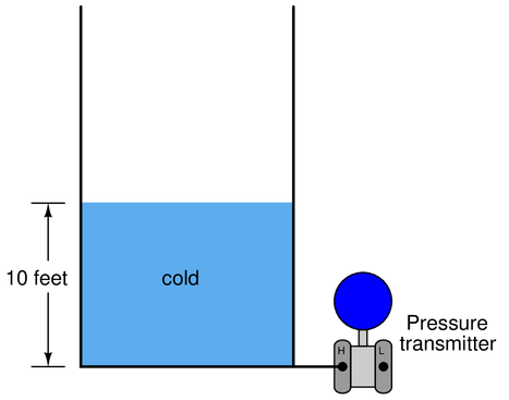
Now, imagine that same vessel being heated until the liquid expands to exactly {\it twice} its former volume:
The liquid level must double to accommodate twice the volume in the same vessel, assuming a vessel of constant diameter, and its density will be cut in half (twice the volume with the same mass). Consequently, the two factors of liquid level change and liquid density change cancel each other out to give the exact same hydrostatic pressure as before. In other words, the transmitter will register the same liquid level as it did when the liquid was cold, and will output the exact same signal, even though the actual vessel level is quite a bit more than it was when cold. Pretty tricky, huh?
-
Question 3
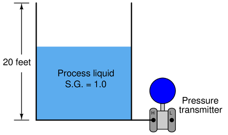
A vessel holding some process liquid needs to have its level monitored. The range of level in this vessel is 0 to 20 feet, and the process liquid has a specific gravity of 1.0 (like water). Someone decides to attach a pressure transmitter to the bottom of the vessel to infer level from hydrostatic pressure like this:
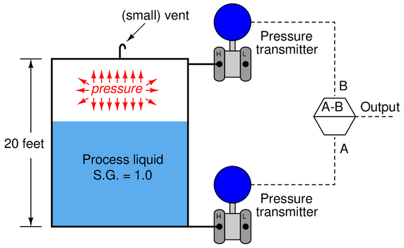
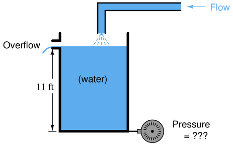
Later, a top is added to this vessel to keep rain from entering in. Unfortunately, though, this process liquid tends to emit vapor which will be trapped by the closed vessel and create a pressure inside of it. A small vent is added to the top of the vessel to permit the vapor to escape, but it is a {\it small} vent, not big enough to ensure a total absence of vapor pressure buildup at all times:
What problem in level measurement will result from there being an occasional vapor pressure buildup inside this vessel? How may this problem be corrected so that the liquid level will be accurately measured at all times?
Reveal answerAny vapor pressure will be sensed by the transmitter and interpreted as increased liquid level!
Two solutions to this problem:
(1) Use two transmitters (one at top of vessel, one at bottom) and electronically subtract their output signals.
\par}
(2) Connect the ``Low’’ side of the one $\Delta$P transmitter to the top of the vessel to naturally compensate for vapor pressure.
\par}
Since the transmitter infers level from the amount of pressure sensed at the bottom of the vessel, any vapor pressure buildup inside the vessel will be falsely interpreted as additional liquid level, since the transmitter senses the {\it sum total} of hydrostatic pressure plus any vapor pressure trapped inside the vessel.
For example, if the process liquid level were at 10 feet (50
In many applications, the gas pressure inside a vessel far exceeds the hydrostatic pressure generated by the column of liquid inside of it, so this problem can be a very serious one in level measurement. We need to fully understand the nature of the problem and how to solve it in order to successfully measure liquid level in many industrial applications.
The solution to this dilemma is to measure the {\it difference} in pressure between the top and bottom of the vessel. We could do this by using two pressure transmitters, one at the top and one at the bottom, and detect hydrostatic pressure by subtracting the top transmitter’s measurement from the bottom transmitter’s measurement. A computer may be used to perform the mathematical subtraction of signals:
Another, more elegant method, incorporates a {\it differential} pressure transmitter with pipe connections to both ends of the vessel. This solution performs the subtraction mechanically, by directly exposing the transmitter’s sensing element to the {\it difference} of two applied pressures:
Because the differential pressure transmitter solution requires only one sensing instrument rather than two, and results in better accuracy because we are only dealing with the inaccuracies of a single instrument rather than the compounded inaccuracies of two instruments (three, if you include the subtraction unit), the differential, or ``d/p’’ solution is the one more widely used.
In this particular level measurement application, a differential pressure instrument would have the exact same calibration points (lower and upper range-values) as a ``normal’’ pressure transmitter connected to an open vessel.
-
Question 4
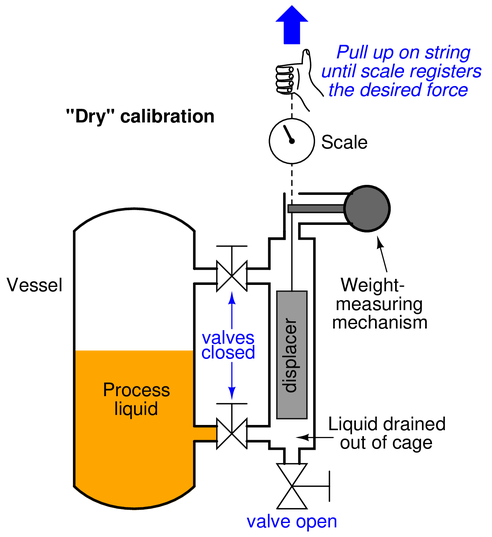
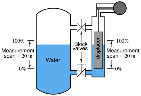
The principle of buoyancy may be used to create a level transmitter instrument, generating an output signal proportional to the change in weight of a ``displacer’’ rod suspended in a liquid:
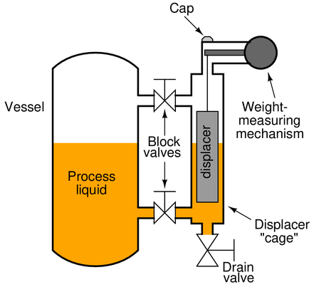
Often, the displacer is housed inside its own ``cage’’ for easy removal from the process, as shown above, or it may be inserted directly into the process vessel like this:
If the vessel is open and the liquid inside is turbulent due to mixing or other agitation, a {\it stilling well} serves the same purpose as a cage:
To calibrate such an instrument, it must be isolated from the process liquid. Sometimes this means simply closing block valves and draining the cage. Other times it means removing the displacer mechanism from the vessel entirely. But once the displacer is hanging dry, there is the problem of simulating a 100
Describe a way to make the displacer ``think’’ it is fully submerged in process liquid when it in fact is hanging freely in the air. Explain how you would be able to {\it precisely} and {\it accurately} simulate this condition, as well as any given condition of partial displacer submersion for that matter.
Reveal answerOne way to simulate a full condition is to use a {\it hand scale}:
-
Question 5
The following storage vessel holds water. The hydrostatic-pressure level transmitter is located 5 feet below the bottom of the vessel, and the desired level measurement range is 8 feet to 12 feet:
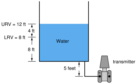
Assuming a pneumatic transmitter with an output range of 3 PSI to 15 PSI, and a calibration accuracy of +/- 1
$$\begin{array} {|l|l|} \hline Process & Percent of & $\Delta$ pressure & Output signal & Output signal & Output signal \\ \hline level (ft) & span ( \\ \hline \ & 0 & & & & \\ \hline & 10 & & & & \\ \hline & 25 & & & & \\ \hline & 50 & & & & \\ \hline & 75 & & & & \\ \hline & 90 & & & & \\ \hline & 100 & & & & \\ \hline \end{array}$$
Reveal answer$$\begin{array} {|l|l|} \hline Process & Percent of & $\Delta$ pressure & Output signal & Output signal & Output signal \\ \hline level (ft) & span ( \\ \hline \8 & 0 & 156 & 3 & 2.88 & 3.12 \\ \hline 8.4 & 10 & 160.8 & 4.2 & 4.08 & 4.32 \\ \hline 9 & 25 & 168 & 6 & 5.88 & 6.12 \\ \hline 10 & 50 & 180 & 9 & 8.88 & 9.12 \\ \hline 11 & 75 & 192 & 12 & 11.88 & 12.12 \\ \hline 11.6 & 90 & 199.2 & 13.8 & 13.68 & 13.92 \\ \hline 12 & 100 & 204 & 15 & 14.88 & 15.12 \\ \hline \end{array}$$
-
Question 6
Determine the LRV and URV settings for the water seal drum lever transmitter (LT-21), assuming the LRV point is at the lower nozzle and the URV point is at the upper nozzle (the two nozzles being 3 feet 8 inches apart from each other), and that the remote seal fill fluid has a specific gravity of 0.934:
 Reveal answer
The elevation for this transmitter (i.e. the total differential pressure applied by the height of fill fluid on both sides) is equal to the total height difference between the remote seal diaphragms multiplied by the specific gravity of the fill fluid:
$$P_{elevation} = (44 \hbox{ in})(0.934) = 41.1 \hbox{ "WC}$$
In the LRV condition, this is the only pressure seen by the transmitter. Therefore, 41.1 “WC is the appropriate LRV setting for this transmitter. If we assume that the ``H’’ port of this DP transmitter connects to the lower nozzle, the LRV will be -44.1 “WC. If we assume the ``H’’ port connects to the upper nozzle, the LRV will be +41.4 “WC.
In the URV condition, we have the exact same amount of elevation (the fill fluid inside the capillary tubes) but on the lower nozzle we have the hydrostatic pressure of 44 vertical inches of water (i.e. the water inside the seal drum). Thus, in the URV condition the transmitter sees a differential pressure of:
$$P_{differential} = 44 \hbox{" WC} - 41.1 \hbox{ "WC} = 2.9 \hbox{ "WC}$$
If we assume the ``H’’ port of this DP transmitter connects to the lower nozzle, the URV will be +2.9 “WC. If we assume the ``H’’ port of this DP transmitter connects to the upper nozzle, the URV will be -2.9 “WC.
 Notes:
This question is a good candidate for a ``Virtual Troubleshooting’’ exercise. Presenting the diagram to students, you first imagine in your own mind a particular fault in the system. Then, you present one or more symptoms of that fault (something noticeable by an operator or other user of the system). Students then propose various diagnostic tests to perform on this system to identify the nature and location of the fault, as though they were technicians trying to troubleshoot the problem. Your job is to tell them what the result(s) would be for each of the proposed diagnostic tests, documenting those results where all the students can see.
During and after the exercise, it is good to ask students follow-up questions such as:
{\bullet} What does the result of the last diagnostic test tell you about the fault?
{\bullet} Suppose the results of the last diagnostic test were different. What then would that result tell you about the fault?
{\bullet} Is the last diagnostic test the best one we could do?
{\bullet} What would be the ideal order of tests, to diagnose the problem in as few steps as possible? -
Question 7
Calculate the hydrostatic pressure generated at the bottom of this vessel (in units of PSI) when it is completely filled with water:
Now calculate the hydrostatic pressure at the bottom of this vessel (in units of PSI) when it is completely filled with gasoline (density = 42 lb/ft$^{3}$):
What do you think the pressure will be at the bottom of the vessel if it is exactly half-full of gasoline and half-full of water, with a gasoline-water {\it interface} at the 5.5 foot mark? Explain your reasoning.
Reveal answerHydrostatic pressure when completely full of water = 4.769 PSI
Hydrostatic pressure when completely full of gasoline = 3.208 PSI
Hydrostatic pressure when water-gasoline interface is at the 50
Notes:{\bf Summary Quiz:}
Calculate the hydrostatic pressure at the bottom of this open vessel, holding 7 feet of gasoline over 6 feet of water:
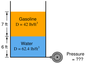
{\bullet} 190.9 inches W.C.
{\bullet} 105.0 inches W.C.
{\bullet} 130.5 inches W.C.
{\bullet} 128.5 inches W.C.
{\bullet} 132.5 inches W.C.
{\bullet} 156.0 inches W.C.
-
Question 8
Calculate the differential pressure sensed by the level transmitter at three different water levels in this boiler steam-drum level measurement system: 0
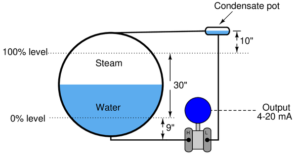
Assume a density for (hot) boiler drum water of 36 lb/ft$^{3}$, a density for steam in the drum of 7 lb/ft$^{3}$, and a density for (warm) water in the ``wet leg’’ of 61.8 lb/ft$^{3}$. If the pressure at the ``low’’ (L) side of the transmitter is greater than the pressure at the ``high’’ (H) side, be sure to express the differential pressure quantity as a negative number.
Credit will be given for correctly calculating each of the differential pressures:
{\bullet} {\bf (6 points)} Transmitter $\Delta$P at 0
{\bullet} {\bf (6 points)} Transmitter $\Delta$P at 50
{\bullet} {\bf (6 points)} Transmitter $\Delta$P at 100Reveal answer{\bullet} {\bf (6 points)} Transmitter $\Delta$P at 0
{\bullet} {\bf (6 points)} Transmitter $\Delta$P at 50
{\bullet} {\bf (6 points)} Transmitter $\Delta$P at 100 -
Question 9
A displacer-type density transmitter registers a displacer weight of 6.3 pounds with the cage completely full of sample liquid. The displacer has a dry weight of 14 pounds, a density of 120 lb/ft$^{3}$, and is cylindrical in shape. Calculate the density of the liquid in units of pounds per cubic foot.
Reveal answerThe liquid has a density of 66 pounds per cubic foot.
-
Question 10
Determine a basic 5-point (0

The cylindrical displacer weighs 15 pounds (dry) and has a diameter of 2 inches. The process liquid is water. The 0
$$\begin{array} {|l|l|} \hline Process & Percent of & Buoyant & Output signal \\ \hline level (in) & span ( \\ \hline \ & 0 & & \\ \hline & 25 & & \\ \hline & 50 & & \\ \hline & 75 & & \\ \hline & 100 & & \\ \hline \end{array}$$
Reveal answer$$\begin{array} {|l|l|} \hline Process & Percent of & Buoyant & Output signal \\ \hline level (in) & span ( \\ \hline \ 0 & 0 & 0 & 4 \\ \hline 10 & 25 & 1.135 & 8 \\ \hline 20 & 50 & 2.270 & 12 \\ \hline 30 & 75 & 3.405 & 16 \\ \hline 40 & 100 & 4.540 & 20 \\ \hline \end{array}$$
-
Question 11
Determine a basic 5-point (0
The cylindrical displacer weighs 9 pounds (dry) and has a diameter of 2 inches. The process liquid is water. The 0
$$\begin{array} {|l|l|} \hline Process & Percent of & Buoyant & Output signal \\ \hline level (in) & span ( \\ \hline \ & 0 & & \\ \hline & 25 & & \\ \hline & 50 & & \\ \hline & 75 & & \\ \hline & 100 & & \\ \hline \end{array}$$
Reveal answer$$\begin{array} {|l|l|} \hline Process & Percent of & Buoyant & Output signal \\ \hline level (in) & span ( \\ \hline \ 0 & 0 & 0 & 4 \\ \hline 5 & 25 & 0.567 & 8 \\ \hline 10 & 50 & 1.135 & 12 \\ \hline 15 & 75 & 1.702 & 16 \\ \hline 20 & 100 & 2.270 & 20 \\ \hline \end{array}$$
