 Facebook
 Google
 GitHub
 Linkedin
Electricity and Electronics
Meter and Instrument Usage
-
Question 1
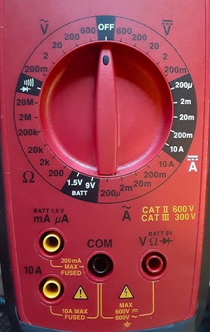
Using the manual-ranging meter image above, select the proper measurement point for verifying 24 vDC signals for a sensor.
Reveal answerThe 200 range on on the DC voltage (upper right) side of the dial.
-
Question 2
Using the manual-ranging meter image above, select the proper measurement point for verifying 120 vAC line voltage to a controller power supply.
Reveal answerThe 200 range on on the AC voltage (upper left) side of the dial.
-
Question 3
A photo sensor datasheet states that the sourcing current output is <250 mA.
1. What is the proper dial setting to measure the current output of the sensor if the sensor is energized?
2. If the sensor is de-energized, what is the proper dial setting for measurement?Reveal answer1. For the on-state current, the 10A DC setting (middle right side of the dial) is most appropriate. 250 mA may destroy the fuse for the mA setting.
Depending on the load (input module) resistance, the actual current may be much less than 250 mA.2. The off-state leakage current should be very, very small. Use the 200u dial setting.
If the value reads 200 uA, move the next highest setting, but verify with a datasheet for the sensor. 200 microamps when switched off is abnormally high and may indicate a defective sensor. -
Question 4
A 3-wire sensor output voltage (black ‘load’ wire) is measured and found to be 0 volts regardless of object presence or not.
Should you first suspect and verify:
1. Faulty sensor requiring replacement
2. Poor adjustment of sensor range
3. Power supply / wiring connection failure
4. Alignment between sensor and object to be sensed has changed (damage?)
Reveal answerOption 3 is the wisest to verify first.
It is the easiest voltage measurement to make right away. Measure the voltage across the + and - wires of the sensor, and you should read 24 volts DC.
If you read 0 volts, there is a bad connection to the + wire somewhere between the sensor and power supply, or the supply is faulty.
If you read something less than 24 volts (anything more than 1-2 volts), the - wire is likely disconnected between the sensor and power supply. Therefore, you are measuring a floating voltage at the + connection.
If the sensor is replaced or adjusted before verifying power, the time was wasted, and the problem will still need to be repaired. Worse, if the adjustment is made with no positive effect, it will simply need to be readjusted back to the right value.
-
Question 5
You suspect that after many years, the contacts of a manual pushbutton are beginning to fail.
What process would you use to verify the contact condition of this button?
Reveal answerLive voltage test (use with caution):
1. Measure the voltage across the terminals of the button.
2. When the button is de-energized and the contacts are open, the voltage should be equal to the control voltage (24 vDC or 120 vAC commonly).
3. When the button is energized, switch to the lowest voltage measurement range of the meter (if applicable) and the voltage should be nearly 0 volts. a few millivolts is acceptable. If the voltage drop across the contacts is excessive, this is due to carbon buildup on the pads from arcing or from corrosion, and excessive voltage drop can cause heating issues in the plastic housing.
Test with voltage removed:
1. Remove at least 1 of the wires from the contact terminals.
2. Measure the resistance across the terminals of the button.
3. When the button is de-energized and the contacts are open, the resistance should be OL (which means overlimit) for all measurement ranges.
3. When the button is energized, switch to the lowest resistance measurement range of the meter (if applicable) and the resistance should be nearly 0 ohms. Once again, a measurement of a few ohms can be caused by corrosion and lead to the voltage drop and excessive heat.
-
Question 6
You wish to measure the current through an 1100 watt heater circuit supplied by a 120 vAC source.
What dial setting on the above manual-ranging meter should you use for this measurement?
Reveal answerYou should not use this meter.
Watt’s Law states that the current is equal to the power divided by the voltage:
$$I={P \over V}$$
$$I={1100~W \over 120~V}$$
$$I=9.2~A$$If there is any significant percent error (more than 10%) in the resistance of the heater, the current could easily exceed the fuse rating of 10 amps.
It would be advisable to locate a clamp-on current meter designed for measuring higher AC current values.
-
Question 7
True or False:
You can measure AC Voltage in either polarity (L and N do not matter).Reveal answerTrue.
The meter will always provide a positive AC voltage indicating the RMS voltage value.
-
Question 8
True or False:
You can measure CD Voltage in either polarity (+ and - do not matter).
Reveal answerPartially true.
You can absolutely measure DC voltage in either polarity. If the ‘COM’ lead’s voltage is higher than the ‘V’ lead’s voltage, the screen will simply show a negative (-) value, but the magnitude is the same.
However, reversing + and - definitely does have an effect on the polarity of the measured value, so it does ‘matter’.
-
Question 9
True or False:
Resistance measurements will always be positive values.
Reveal answerFalse.
They should always be positive, but the meter can display negative resistance values.
Notes:The battery of the meter supplies voltage, which is dropped in series between the unknown measured resistor and the fixed internal resistance; a voltage divider, in other words.
Both resistors will drop less than the battery voltage, so the resistance can be calculated for the unknown series resistor.
If you accidentally measure an energized circuit, the voltage across the unknown series resistor may exceed the battery voltage, and the only way to complete the series voltage sum and satisfy Kirchhoff’s Voltage Law is to compute a negative value for the unknown resistor.
If you see a negative resistance, quickly remove the meter and isolate the resistor.
