 Facebook
 Google
 GitHub
 Linkedin
Instrumentation and Process Control
PID Loop Tuning
-
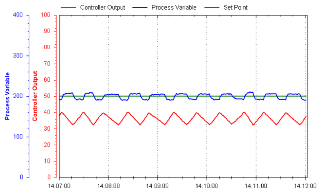
Question 1
Examine this process trend showing the PV, SP, and Output of a loop controller:
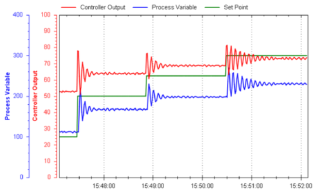
Based on what you see here, determine the following:
{\bullet} Whether this is an open-loop or a closed-loop response
{\bullet} Whether the controller is (or needs to be) direct-acting or reverse-acting
{\bullet} If possible, identify any problems with the field instrumentation
{\bullet} If possible, identify any problems with the controller PID tuning
{\bullet} Qualitatively identify the kind of PID tuning we will need for robust controlReveal answerThis is a closed-loop test, based on the fact the output signal responds dynamically to the changing process variable, as well as to the step-change in setpoint.
This is a reverse-acting controller: the output steps up when the setpoint steps up (implying the output would step down if the process variable stepped up).
There do not appear to be any field instrumentation problems revealed in this trend. A manual-mode (open-loop) test would be more informative in that regard, but it appears as though the process is very quick to respond with no discernable dead time or other lags.
The controller tuning is clearly inappropriate for this process. Note the large offset between PV and SP (i.e. how the process variable never settles at the setpoint value, even though it’s clearly a fast-responding process). This tells us the controller is configured only for proportional action, and this process needs integral! We can also tell this from the 180$^{o}$ phase shift between PV and output during the oscillations: this is the classic response of a reverse-acting proportional-only controller with excessive gain.
Aggressive integral action with a minimum of proportional gain should work very well in this process, which is probably a liquid flow-control process.
Notes:Reference educational articles:
-
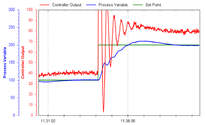
Question 2
Examine this process trend showing the PV, SP, and Output of a loop controller:
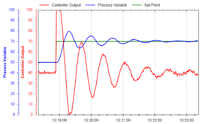
Based on what you see here, determine the following:
{\bullet} Whether this is an open-loop or a closed-loop response
{\bullet} Whether the controller is (or needs to be) direct-acting or reverse-acting
{\bullet} If possible, identify any problems with the field instrumentation
{\bullet} If possible, identify any problems with the controller PID tuning
{\bullet} Qualitatively identify the kind of PID tuning we will need for robust controlReveal answerThis is a closed-loop test, based on the fact the output signal responds dynamically to the changing process variable, as well as to the step-change in setpoint.
This is a reverse-acting controller: the output steps up when the setpoint steps up (implying the output would step down if the process variable stepped up).
There do not appear to be any field instrumentation problems revealed in this trend. A manual-mode (open-loop) test would be more informative in that regard, but it appears as though the process is very quick to respond with no discernable dead time or other lags.
The controller tuning is too heavy on proportional action. We can tell this from the phase shift between PV and output during the oscillations, which is nearly 180$^{o}$. Excessive integral action would shift the phase of the output wave further to the right (i.e. so that each peak of the output waveform coincided with the zero-crossing of the PV waveform, or very nearly). The fact that the inverse peaks of the PV and output waves are very nearly aligned tells us that excessive gain (proportional action) is the culprit here. Another clue is the magnification of noise we see in the output trend compared to the PV trend—only proportional action or derivative action can cause this, and since we see no sign of excessive derivative action (e.g. output wave leading the PV wave), we can safely say the problem is too much gain.
The process response time (dead time, lag time) seems to be very short, which is a good thing for process control. We can tell, however, that this is an {\it integrating} process by the way it was able to achieve a new SP value with the old output value. This means it will exhibit some overshoot with SP changes if there is any integral action. We may have to do most of the control through proportional action (albeit much less gain than we are using now!), with just enough integral action to handle load changes.
Notes:Reference educational articles:
-
Question 3
Examine this process trend showing the PV, SP, and Output of a loop controller:
Based on what you see here, determine the following:
{\bullet} Whether this is an open-loop or a closed-loop response
{\bullet} Whether the controller is (or needs to be) direct-acting or reverse-acting
{\bullet} If possible, identify any problems with the field instrumentation
{\bullet} If possible, identify any problems with the controller PID tuning
{\bullet} Qualitatively identify the kind of PID tuning we will need for robust controlReveal answerThis is a closed-loop test, based on the fact the output signal responds dynamically to the changing process variable, as well as to the step-change in setpoint.
This is a reverse-acting controller: the output steps up when the setpoint steps up (implying the output would step down if the process variable stepped up).
This process does exhibit some dead time as well as lag time, which explains the setpoint overshoot. A field check of the control element (valve) might be good to do, so see that it is not sticking and causing dead time.
The controller tuning actually looks pretty good here. The only problem is the slight overshoot of setpoint, which may or may not be significant depending on the specific process and the needs of operations personnel. If this overshoot is deemed excessive, we might wish to turn down the proportional action (gain), based on the fact the PV and output waves seem to hit their respective peaks at nearly the same time (characteristic of proportional-dominant action).
Given the existence of dead time and lag time together, we must be careful not to use too much proportional action lest the loop oscillate. Derivative action could be very useful in taming the effects of lag time.
Notes:Reference educational articles:
-
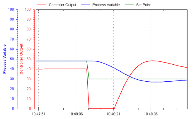
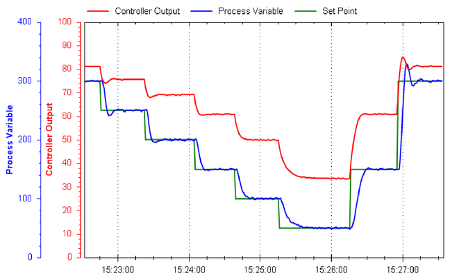
Question 4
Examine this process trend showing the PV, SP, and Output of a loop controller:
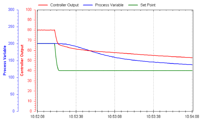
Based on what you see here, determine the following:
{\bullet} Whether this is an open-loop or a closed-loop response
{\bullet} Whether the controller is (or needs to be) direct-acting or reverse-acting
{\bullet} If possible, identify any problems with the field instrumentation
{\bullet} If possible, identify any problems with the controller PID tuning
{\bullet} Qualitatively identify the kind of PID tuning we will need for robust controlReveal answerThis is a closed-loop test, based on the fact the output signal responds dynamically to the changing process variable, as well as to the step-change in setpoint.
This is a reverse-acting controller: the output steps up when the setpoint steps up (implying the output would step down if the process variable stepped up).
There do not appear to be any field instrumentation problems revealed in this trend. A manual-mode (open-loop) test would be more informative in that regard, and it appears as though the process possesses a multiple-order lag, but the time scale of this lag seems modest. It might not be a bad idea to look around for sources of lag time (e.g. thermowell mass, improperly inserted temperature probe), just to see if the response time might be improved a bit. Another possibility explaining the lag time would be a transmitter (or controller input block) configured with too much filtering (damping), adding a single-order lag to whatever lag(s) the process itself already possesses.
The controller tuning is clearly inappropriate for this process, and should be much more aggressive than it is right now. Note how the PV is taking a long time to reach the new SP, and how the controller output is ramping down at a very leisurely pace.
This process appears to be self-regulating, and so we know we must have some integral action in the controller. The existence of multiple-order lag makes this loop a good candidate for moderate derivative action.
Notes:Reference educational articles:
-
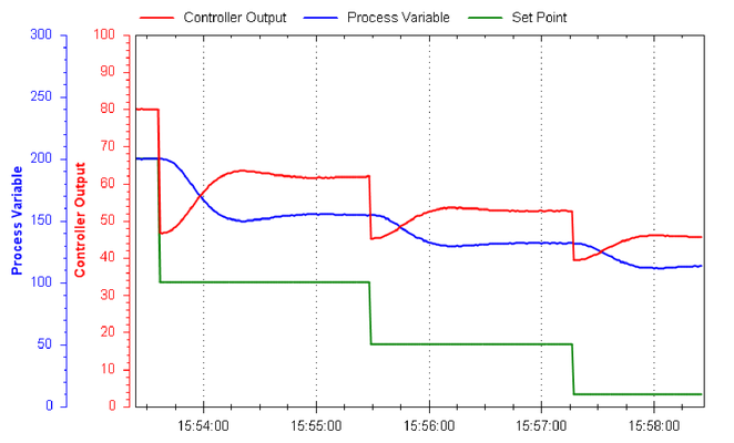
Question 5
Examine this process trend showing the PV, SP, and Output of a loop controller:
Based on what you see here, determine the following:
{\bullet} Whether this is an open-loop or a closed-loop response
{\bullet} Whether the controller is (or needs to be) direct-acting or reverse-acting
{\bullet} If possible, identify any problems with the field instrumentation
{\bullet} If possible, identify any problems with the controller PID tuning
{\bullet} Qualitatively identify the kind of PID tuning we will need for robust controlReveal answerThis is a closed-loop test, based on the fact the output signal responds dynamically to the changing process variable, as well as to the step-change in setpoint.
This is a reverse-acting controller: the output ramps up whenever the PV is below SP, and the output ramps down whenever the PV is above SP.
This loop definitely has hysteresis in the final control element (e.g. sticky valve), because this trend is a classic slip-stick cycle in a self-regulating process: the PV exhibits a square-wave shape while the output ramps up and down like a sawtooth wave.
There probably isn’t anything wrong with the controller’s tuning, and no tuning adjustments will fundamentally address the problem of valve stiction.
The process appears to be self-regulating with a fast response time (note how quickly the PV settles at a new value following each ``slip’’ of the control valve), which means it should control very well with aggressive integral action. However, final control element hysteresis is the bane of integral action, as it causes repeated reset windup as we see here.
Notes:Reference educational articles:
-
Question 6
Examine this process trend showing the PV, SP, and Output of a loop controller:
Based on what you see here, determine the following:
{\bullet} Whether this is an open-loop or a closed-loop response
{\bullet} Whether the controller is (or needs to be) direct-acting or reverse-acting
{\bullet} If possible, identify any problems with the field instrumentation
{\bullet} If possible, identify any problems with the controller PID tuning
{\bullet} Qualitatively identify the kind of PID tuning we will need for robust controlReveal answerThis is a closed-loop test, based on the fact the output signal responds dynamically to the changing process variable, as well as to the step-change in setpoint.
This is a reverse-acting controller: the output steps up when the setpoint steps up (implying the output would step down if the process variable stepped up).
There do not appear to be any field instrumentation problems revealed in this trend. A manual-mode (open-loop) test would be more informative in that regard, but it appears as though the process is very quick to respond with little dead time or other lags.
The controller tuning is clearly too aggressive for this process. Note the “porpoising” action of the PV as it approaches SP following the SP step-change. Only two types of controller action can cause this to occur: proportional, or derivative. Porpoising is when an oscillation occurs in the PV prior to it crossing setpoint, which explains why integral action cannot ever be to blame for porpoising: the only way a loop oscillation can occur is when the final control element oscillates as well (i.e. changes direction), and since integral action will never change direction until PV crosses SP, oscillations that occur on one side of SP cannot be caused by integral action. Looking at the phase shift between PV and output during the oscillations, it appears the output peaks may slightly lead the PV peaks, but only slightly. This suggests that proportional is the action that is too aggressive (if it were derivative, there would be more of a leading phase shift).
This is definitely a self-regulating process, as revealed by the fact a new output value is required to achieve a new setpoint value. This means integral control action will definitely be necessary. Good control will require less gain and perhaps a bit more derivative action to help cancel the lag. Integral action looks just fine where it is right now, with just a little SP overshoot.
Notes:Reference educational articles:
-
Question 7
Examine this process trend showing the PV, SP, and Output of a loop controller:
Based on what you see here, determine the following:
{\bullet} Whether this is an open-loop or a closed-loop response
{\bullet} Whether the controller is (or needs to be) direct-acting or reverse-acting
{\bullet} If possible, identify any problems with the field instrumentation
{\bullet} If possible, identify any problems with the controller PID tuning
{\bullet} Qualitatively identify the kind of PID tuning we will need for robust controlReveal answerThis is a closed-loop test, based on the fact the output signal responds dynamically to the changing process variable, as well as to the step-change in setpoint.
This is a reverse-acting controller: the output steps up when the setpoint steps up (implying the output would step down if the process variable stepped up).
The only problem here is that the process exhibits a varying gain. This is why the control is over-sensitive (oscillatory) at high setpoint values and sluggish at low setpoint values. This could be a function of process dynamics, or of a control valve with the wrong characteristic (e.g. an equal-percentage valve in an application better suited for a linear valve).
The controller tuning looks really good when the process variable is maintaining around 40
This process appears to be self-regulating with short dead and lag times. It is clear from examining the phase shifts of output versus PV that there is some derivative action at work here, since the output actually leads the PV when there is oscillation. The key will be linearizing the process gain so that one set of tuning parameters will work robustly across the control range.
Notes:Reference educational articles:
-
Question 8
Examine this process trend showing the PV, SP, and Output of a loop controller:
Based on what you see here, determine the following:
{\bullet} Whether this is an open-loop or a closed-loop response
{\bullet} Whether the controller is (or needs to be) direct-acting or reverse-acting
{\bullet} If possible, identify any problems with the field instrumentation
{\bullet} If possible, identify any problems with the controller PID tuning
{\bullet} Qualitatively identify the kind of PID tuning we will need for robust controlReveal answerThis is a closed-loop test, based on the fact the output signal responds dynamically to the changing process variable, as well as to the step-change in setpoint.
This is a reverse-acting controller: the output steps up when the setpoint steps up (implying the output would step down if the process variable stepped up).
There do not appear to be any field instrumentation problems revealed in this trend. A manual-mode (open-loop) test would be more informative in that regard, but it appears as though the process is very quick to respond with no discernable dead time or other lags.
The controller tuning is clearly lacking integral action. Note the large offset between PV and SP (i.e. how the process variable never settles at the setpoint value). This tells us the controller is configured only for proportional action, and this process needs integral! We can also tell this from the 180$^{o}$ phase shift between PV and output during the oscillations: this is the classic response of a reverse-acting proportional-only controller. The actual amount of gain appears to be appropriate for the loop, since the oscillations are not excessive.
We desperately need to apply some integral action to this loop, because self-regulating loops absolutely need integral action to handle load changes and achieve new setpoint values.
Notes:Reference educational articles:
