 Facebook
 Google
 GitHub
 Linkedin
Instrumentation and Process Control
Pressure-based Flowmeter Calculations
-
Question 1
A pitot tube measuring the flow of glycerin (78.6 lb/ft$^{3}$) produces a differential pressure of 35 “WC (inches of water column) at a mass flow rate of 450 pounds per minute.
Calculate the differential pressure produced by this same Pitot tube at a flow rate of 310 lb/min.
Calculate the mass flow rate at a differential pressure of 12.6 “WC.
If the glycerin density happens to change from 78.6 lb/ft$^{3}$ to 75.1 lb/ft$^{3}$, calculate the mass flow rate at a differential pressure of 24.8 “WC.
Reveal answerDifferential pressure produced by this same Pitot tube at a flow rate of 310 lb/min = 16.61 “WC
Mass flow rate at a differential pressure of 12.6 “WC = 270 lb/min
Mass flow rate at DP of 24.8 “WC, assuming a density of 75.1 lb/ft$^{3}$ = 370.3 lb/min
-
Question 2
A pneumatic DP transmitter measures the flow of gasoline through a an orifice plate, using a separate square root extractor relay to characterize the signal so that it may be displayed linearly on the receiver gauge (FI-20):

Based on other flow-measuring devices in this process, operations personnel have determined the actual flow rate through this pipe is 158 gallons per minute. FI-20, however, registers a flow of 142 gallons per minute. Based on the data you see in this illustration, determine the location of the calibration error.
Reveal answerThe error lies either with the DP transmitter (FT-20), unequal fluid inside the impulse tubes, or with the orifice plate itself (FE-20). One quick check would be to drain the impulse tubes (allowing fresh process gasoline to fill the tubes) and seeing whether that fixes the problem. It’s a quick procedure and it would eliminate that problem from the realm of possibility.
Another way to diagnose the problem is to remove FT-20 from service and test its calibration with applied pressures to its “H” side port. If FT-20 checks out okay, the problem must be with the impulse tubes or the orifice plate.
-
Question 3
A pneumatic DP transmitter measures the flow of gasoline through a an orifice plate, using a separate square root extractor relay to characterize the signal so that it may be displayed linearly on the receiver gauge (FI-20):
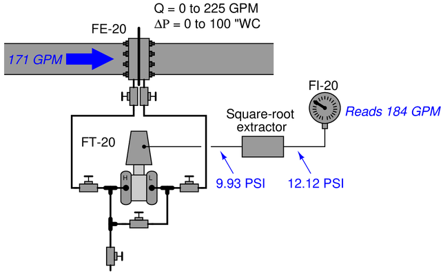
Based on other flow-measuring devices in this process, operations personnel have determined the actual flow rate through this pipe is 171 gallons per minute. FI-20, however, registers a flow of 184 gallons per minute. Based on the data you see in this illustration, determine the location of the calibration error.
Reveal answerThe error lies with the indicator (FI-20).
-
Question 4
A “smart” DP transmitter with built-in square root characterization is used to measure flow through a pipe. The orifice plate range is 0 to 125 inches WC at 0 to 277 gallons per minute:

A technician removes the transmitter from service and tests it by applying several air pressures to the ``H’’ port while leaving the “L” port vented. Here are the As-Found results:
$$\begin{array} {|l|l|} \hline Applied~Pressure~(“WC) & Current~signal~(mA) \\ \hline 0 & 4.020 \\ \hline 31.25 & 12.060 \\ \hline 62.5 & 15.390 \\ \hline 93.75 & 17.946 \\ \hline 125 & 20.100 \\ \hline \end{array}$$
Reveal answerThis is a span error in the output (DAC) of the smart transmitter, the greatest error being at the 100
-
Question 5
A “smart” DP transmitter with built-in square root characterization is used to measure flow through a pipe. The orifice plate range is 0 to 125 inches WC at 0 to 277 gallons per minute:
A technician removes the transmitter from service and tests it by applying several air pressures to the “H” port while leaving the ``L’’ port vented. Here are the As-Found results:
$$\begin{array} {|l|l|} \hline Applied~Pressure~(“WC) & Current~signal~(mA) \\ \hline 0 & 5.431 \\ \hline 31.25 & 12.127 \\ \hline 62.5 & 15.404 \\ \hline 93.75 & 16.128 \\ \hline 125 & 20.064 \\ \hline \end{array}$$
Reveal answerThis is a zero error in the input (ADC) of the smart transmitter, the greatest error being at the 0
-
Question 6
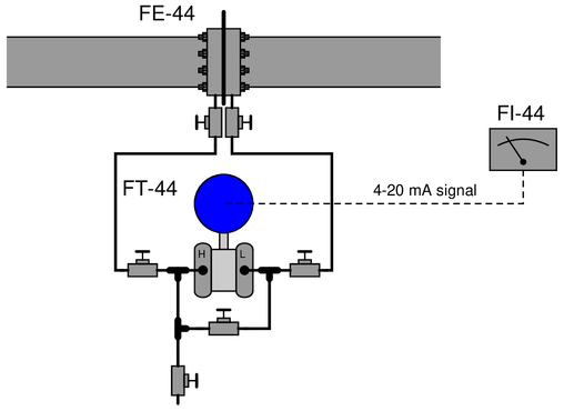
A “smart” DP transmitter with built-in square root characterization is used to measure flow through a pipe. The orifice plate range is 0 to 150 inches WC at 0 to 480 gallons per minute:

Operations personnel have strong reason to believe that the actual flow rate through this pipe is 160 GPM, yet the DCS registers a flow rate of 182.4 GPM. Based on this information, determine the likely source of calibration error in this system. Also determine whether this transmitter has square-root characterization enabled or not.
Additionally, suggest a good “next step” to perform to either pinpoint the location of this problem or correct it.
Reveal answerThe calibration error lies either with the transmitter, the impulse lines (unequal fluid heights inside), or with the orifice plate itself. The transmitter does have square-root characterization enabled.
A good “next step” would be to block and equalize the transmitter manifold to check what its PV and AO parameters register with no applied differential pressure.
-
Question 7
A “smart” DP transmitter and orifice plate were recently installed to measure flow through a pipe. The orifice plate range is 0 to 150 inches WC at 0 to 1000 gallons per minute:
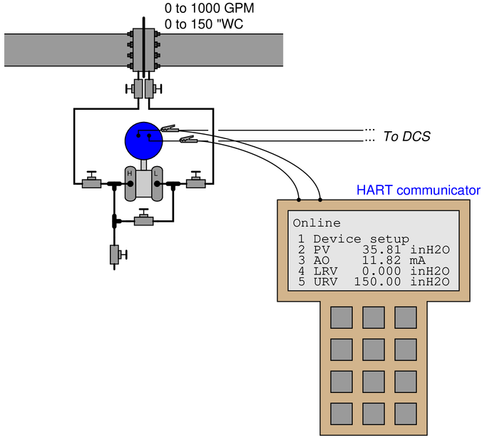
Operations personnel register a flow rate of 699 gallons per minute on the display of their DCS, which they believe to be too much. Based on what you see here, do you think there is a problem, or is this new system working as it should?
Reveal answerThe problem lies with the DCS: to be specific, someone has configured square-root characterization in it as well as within the transmitter!
