 Facebook
 Google
 GitHub
 Linkedin
Instrumentation and Process Control
Pumps and Compressors
-
Question 1
The compressor emergency shutdown system (ESD) has tripped the natural gas compressor off-line three times in the past 24 hours. Each time the operator goes to reset the compressor interlock, she notices the graphic display panel on the interlock system says “Separator boot high level” as the reason for the trip. After this last trip, operations decides to keep the compressor shut down for a few hours until your arrival to diagnose the problem. Your first diagnostic test is to look at the indicated boot level in the sightglass (LG-93). There, you see a liquid level appears to be normal:

First, explain why this first diagnostic test was a good idea. Then, identify what would your next diagnostic test be.
Finally, comment on the decision by operations to leave the compressor shut down until your arrival. Do you think this was a good idea or a bad idea, from a diagnostic perspective? Why or why not?
Reveal answerGiven the fact that the ESD system keeps indicating a high boot level, you know that it “thinks” the liquid level inside the boot is higher than it should be. The next logical step is to determine whether or not a high liquid level condition does indeed exist. If so, the trip is legitimate and there may be a problem with the liquid level control system. If not, the LSHH-231 or its associated wiring may have a fault that sends a false trip alarm to the ESD system.
However, the decision to leave the compressor idle for a few hours until your arrival was not a good one for diagnosis. If indeed there is a problem with excessive liquid collecting in the boot, this would only be evident during running operation. With the compressor idle and no new gas entering the separator vessel, there will be no new liquid collecting in the boot, which will give the boot level control system ample time to empty that liquid down to a normal level and make it appear as though there is no level problem. In other words, leaving the compressor idle for a few hours “erases” the evidence, making it more difficult to troubleshoot.
Aside from re-starting the compressor and watching it run, you could perform a test on the liquid level control system by simulating a high-level condition inside the boot (e.g. applying pressure to one side of LT-92) and observing how fast or slow the actual liquid drains out (as indicated by LG-93). If there is a problem with the level control valve LV-92 or its associated components, you should be able to tell in the form of a long (slow) drain time. The fact that the blind flange at the bottom of the boot drain line says “Rod out” on the P&ID suggests this line is prone to plugging with debris, which could explain a slow-draining condition and consequently the frequent high-level trips.
Notes:This question is a good candidate for a “Virtual Troubleshooting” exercise. Presenting the diagram to students, you first imagine in your own mind a particular fault in the system. Then, you present one or more symptoms of that fault (something noticeable by an operator or other user of the system). Students then propose various diagnostic tests to perform on this system to identify the nature and location of the fault, as though they were technicians trying to troubleshoot the problem. Your job is to tell them what the result(s) would be for each of the proposed diagnostic tests, documenting those results where all the students can see.
During and after the exercise, it is good to ask students follow-up questions such as:
{\bullet} What does the result of the last diagnostic test tell you about the fault?
{\bullet} Suppose the results of the last diagnostic test were different. What then would that result tell you about the fault?
{\bullet} Is the last diagnostic test the best one we could do?
{\bullet} What would be the ideal order of tests, to diagnose the problem in as few steps as possible? -
Question 2
The compressor automatically shut down last night, tripped by LSHH-231. The control system alarm log showed a high level alarm LIR-92 about 15 minutes prior to the shutdown:
Identify the likelihood of each specified fault in this process. Consider each fault one at a time (i.e. no coincidental faults), determining whether or not each fault could independently account for all measurements and symptoms in this process.
$$\begin{array} {|l|l|} \hline Fault & Possible & Impossible \\ \hline 2-inch~line~plugged~at bottom~of~separator~vessel & & \\ \hline LT-92~failed~with~high~output~signal & & \\ \hline Air~supply~to~solenoid~valve~shut~off & & \\ \hline Solenoid~vent~line~plugged & & \\ \hline PSV-11~stuck~open~& & \\ \hline LSHH-231~failed~with~high~output~signal & & \\ \hline \end{array}$$
Reveal answer$$\begin{array} {|l|l|} \hline Fault & Possible & Impossible \\ \hline 2-inch~line~plugged~at bottom~of~separator~vessel & \surd & \\ \hline LT-92~failed~with~high~output~signal & & \surd \\ \hline Air~supply~to~solenoid~valve~shut~off & \surd & \\ \hline Solenoid~vent~line~plugged & & \surd \\ \hline PSV-11~stuck~open~& & \surd \\ \hline LSHH-231~failed~with~high~output~signal & & \surd \\ \hline \end{array}$$
Notes:From all the evidence, it seems we really had a high-high level condition in the separator boot, and that the shutdown system acted precisely as it was designed to do: protect the compressor from sucking in any liquid.
A good “next test” to do would be to place controller LIC-92 in manual mode and attempt to cycle control valve LV-92, while monitoring solenoid valve SV-92. If these valves function as they should, the problem may be an obstruction in the drain line. If they do not function as they should, the problem is either in one of those valves or in the wiring/tubing connecting those valves to the rest of the system.
This question is a good candidate for a “Virtual Troubleshooting” exercise. Presenting the diagram to students, you first imagine in your own mind a particular fault in the system. Then, you present one or more symptoms of that fault (something noticeable by an operator or other user of the system). Students then propose various diagnostic tests to perform on this system to identify the nature and location of the fault, as though they were technicians trying to troubleshoot the problem. Your job is to tell them what the result(s) would be for each of the proposed diagnostic tests, documenting those results where all the students can see.
During and after the exercise, it is good to ask students follow-up questions such as:
{\bullet} What does the result of the last diagnostic test tell you about the fault?
{\bullet} Suppose the results of the last diagnostic test were different. What then would that result tell you about the fault?
{\bullet} Is the last diagnostic test the best one we could do?
{\bullet} What would be the ideal order of tests, to diagnose the problem in as few steps as possible? -
Question 3
This amount of vacuum (negative pressure) in this knock-out drum is controlled by varying the compressor’s bypass valve:
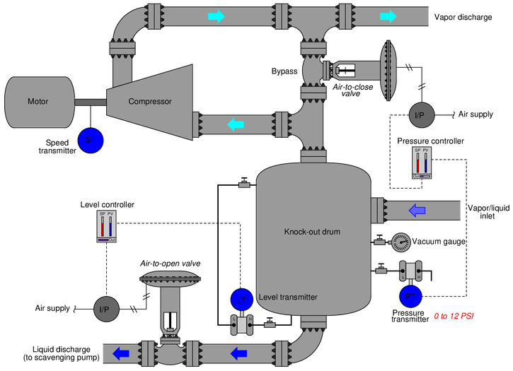
An operator tells you there is a problem with this system, though: the vacuum gauge near the pressure transmitter registers -6.9 PSI, even though the controller faceplate registers -8.0 PSI which is the same as the setpoint. The same operator notes that the control valve position is approximately 30
Another instrument technician happens to be with you, and recommends the operator place the pressure controller in manual mode to “stroke-test” the control valve. Explain why this test would be a waste of time, and propose a better test for helping to pinpoint the location of the fault.
{\bullet} A valuable principle to apply in a diagnostic scenario such as this is correspondence: identifying which field variables correspond with their respective controller faceplate displays, and which do not. Apply this comparative test to the scenario described, and use it to explain why the technician’s proposed test was probably not the best first step.
{\bullet} A problem-solving technique useful for analyzing control systems is to mark the PV and SP inputs of all controllers with “+” and “-” symbols, rather than merely label each controller as “direct” or “reverse” action. Apply this technique to the control strategy shown here, identifying which controller input(s) should be labeled “+” and which controller input(s) should be labeled “-”.
{\bullet} Predict the effects resulting from one of the transmitters in this system failing with either a high or a low signal.
{\bullet} For those who have studied level measurement, explain how the level transmitter (which is nothing more than a DP transmitter) senses liquid level inside the knock-out drum.Reveal answerThe reason that the technician’s proposed test would have been a waste of time is because the issue at hand is a significant disagreement between the vacuum gauge and the controller display. No valve problem or controller output problem could cause this to happen.
A far better test would be to place the pressure controller in manual mode, then vent the pressure transmitter to check that the controller reads 0 PSI. If there is a transmitter calibration problem, it will likely appear as a zero error (not reading 0 PSI at 0 PSI).Alternatively, one could also perform the same test on the vacuum gauge to see if it is in error.
The level controller needs to be direct-acting. The pressure controller needs to be reverse-acting.
Although there is a discrepancy between the controller’s output (displayed) and the actual valve position, an error of (approximately) 1.4
-
Question 4
This compressor control system uses a pressure transmitter and controller to regulate the discharge pressure to a constant setpoint, allowing either a power controller (JIC) or a suction pressure controller (PIC) to override. The power controller overrides the discharge pressure controller under conditions of high load, throttling back the suction valve to limit power. The suction pressure controller overrides them all under conditions of high inlet vacuum, opening the suction valve in order to ensure the compressor’s gland seals are not ruined by excessive vacuum:

In the event of a high inlet vacuum condition simultaneous with a high load condition, the suction pressure controller will “win” by overriding the power controller. Alter this system so that the override priority is vice-versa: the power controller is able to override the suction pressure controller, yet the suction controller is still able to override the discharge controller.
-
Question 5
The following loop diagram shows a compressor surge control system. When the flow controller (FIC 42) detects a condition of high differential pressure across the compressor and a simultaneous condition of low flow through the compressor, it responds by opening the surge control valve (FV 42), bypassing flow from the outlet of the compressor directly back to the input of the compressor:

If the screw on terminal JB1-4 were to come loose, breaking the connection between the two wires joined at that point, what would this surge control valve do, and what effect do you think that would have on the compressor?
{\bullet} Identify whether FV-42 is fail-open (FO) or fail-closed (FC).
{\bullet} What do the short arrows represent (located next to the individual instrument bubbles) in this loop diagram?Reveal answerIf the screw on JB1-4 were to come loose, it would interrupt the current to the I/P transducer, thus making its pneumatic output fail low. We know this because the upward-pointing arrow next to FY-42b denotes it as direct-acting (more mA = more air pressure out). With low air pressure to the bypass valve, the valve will fail open (as indicated by the arrow on the valve stem symbol). This will bypass flow from output to input on the compressor, reducing the amount of gas flow to the process.
For your information, compressor surge is a fluid dynamic phenomenon whereby the blades in a non-positive-displacement compressor (e.g. axial or centrifugal vane) “stall” just like the wings of an airplane flying too slowly and/or at too great an angle of attack. When the blades of a compressor stall, they lose “traction” on the compressed gas, unloading the mechanical driver (engine, motor, or turbine) and allowing the compressor to gain speed, then the blades will “un-stall” and re-load the driver, continuing the cycle.
The following passage is taken from Francis Shinskey’s excellent book Energy Conservation and Control, published by Academic Press in 1978, describing compressor surge:
“The most demanding aspect of controlling compressors is surge protection. The problem lies in being unable to determine with absolute certainty the degree of approach to surge. Once a compressor begins to surge, it will continue until corrective action is applied, so automatic protection is mandatory. A small centrifugal compressor may surge several times without damage, but a 100,000-hp axial could require reblading after a single incident.”
“When a compressor begins to surge, the suction flow falls to zero within a few milliseconds, reverses momentarily, and begins to recover in less than a half second. If the situation is not corrected, the cycle repeats immediately, resulting in a series of thunderclaps less than a second apart. The sudden fall in suction flow can be detected and used to open a recirculating valve, but not before at least one surge cycle is sustained. To prevent surge from developing at all requires a control system which skirts the unstable area altogether.”
-
Question 6
Examine this natural gas compressor system with inlet separator vessel:
Examine this P&ID and answer the following questions:
{\bullet} Why is it important that the separator vessel be placed upstream of the compressor? Why not place it on the discharge side of the compressor instead?
{\bullet} What might cause the compressor to vibrate excessively, thus requiring a vibration monitoring system?
{\bullet} What effect will opening the recycle valve (XV-76) have on the effective compression ratio of this compressor as it is operating?
{\bullet} What measured variables in this system might indicate that the compressor is being overloaded (i.e. working too hard as it tries to compress more natural gas than it safely can)?
Reveal answer{\bullet} Why is it important that the separator vessel be placed upstream of the compressor? Why not place it on the discharge side of the compressor instead? Liquids are incompressible, and so the purpose of the upstream separator vessel is to capture any entrained liquid droplets condense before they would have any chance of entering the compressor.
{\bullet} What might cause the compressor to vibrate excessively, thus requiring a vibration monitoring system? Any damage or wear to the compressor’s rotating pieces causing it to become imbalanced.
{\bullet} What effect will opening the recycle valve (XV-76) have on the effective compression ratio of this compressor as it is operating? Recycling gas through the compressor will reduce the net flow in this natural gas system as well as reduce the amount of differential pressure across the compressor. Both of these effects will reduce the effective compression ratio of the compressor.
{\bullet} What measured variables in this system might indicate that the compressor is being overloaded (i.e. working too hard as it tries to compress more natural gas than it safely can)? Excessive differential pressure (sensed by PDT-77), excessive discharge temperature (sensed by TT-232), excessive electrical power drawn by the compressor’s motor (sensed by JT-220).
-
Question 7
This control system measures and regulates the amount of differential pressure across a gas compressor, by opening a recirculation valve to let high-pressure discharge gas go back to the low-pressure “suction” of the compressor. This control system needs to be very fast-acting, and currently it is anything but that, as revealed by the open-loop trend shown in the upper-right of this illustration:
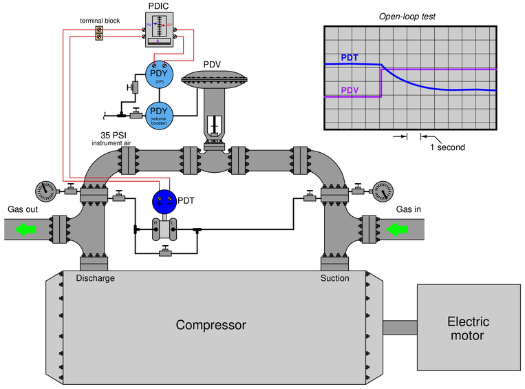
Identify what type of problem you think you are dealing with here, as the compressor’s differential pressure should not take several seconds to stabilize following a sudden move by the recirculation valve. Also suggest a next diagnostic test or measurement to take, explaining how the result(s) of that test help further identify the location and/or nature of the fault.
{\bullet} Based on the evidence presented, how do you know this problem is definitely not caused by poor PID controller tuning?
{\bullet} What other methods exist for controlling differential pressure across a large gas compressor, other than using a recirculation valve?
Reveal answerA good step to take next is to figure out whether the problem is on the output side of the control system or on the input side of the control system. Is the slow pressure trend real, and the control valve not responding as quickly as it should? Is the pressure actually changing quickly, but the measurement side of the system not accurately reporting it as it should?
Probably the best first-step here is to actually go to the control valve and observe how fast it responds to step-changes from the controller (manual mode).
-
Question 8
This control system measures and regulates the differential pressure across a large motor-driven gas compressor by “recycling” gas from the compressor’s discharge line back to its suction line. It uses an air-to-close control valve so that the valve will fail open in the event of air pressure or signal loss. The controller’s output indication, however, is reverse-responding so that 0
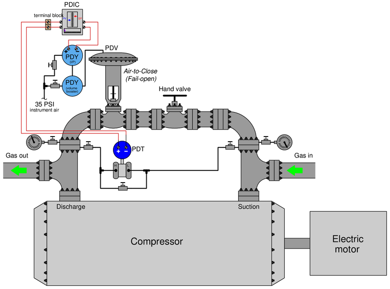
Unfortunately, this system has a problem. The pressure differential indicating controller (PDIC) shows the process variable (PV) being about 50
Identify which of these four areas of the system the problem may be located in, and then describe a good test you could do in or to this system to narrow the problem location even further:
{\bullet} Problem with the measurement side (transmitter, wiring, controller analog input)?
{\bullet} Problem with the controller’s control action (its “decision-making”)?
{\bullet} Problem with the final control element side (valve, I/P, booster, controller analog output)?
{\bullet} Problem with the compressor itself (or other portions of the process)?
{\bullet} Could a shut recycle line hand valve account for what we’re seeing here? Explain why or why not.
Reveal answerThe problem is clearly not with the controller’s action, because according to the faceplate displays it is trying to do the right thing (i.e. shut the control valve to build up differential pressure).
The measurement side of the system may be falsely registering a low pressure (i.e. the pressure is actually greater than what the controller shows), or the valve is opening when it should not (i.e. it is causing the differential pressure to be this low), or the compressor may be performing poorly and not be able to raise the required differential pressure, or the larger process may be drawing too heavily on the compressor.
A good test would be to see whether the differential pressure is actually as low as the controller shows. Another test would be to see whether the control valve is actually open when it should be shut. Using a milliammeter to measure either PV or output signal (mA) would be an excellent place to begin, to verify the controller’s I/O signals and check for correspondence between the controller’s display and the signals.
-
Question 9
Suppose a compressor is operating with the following suction and discharge parameters:
Suction:
{\bullet} Pressure = 45 PSIG
{\bullet} Volumetric flow = 1300 CFM
{\bullet} Temperature = 74 deg FDischarge:
{\bullet} Pressure = 281 PSIG
{\bullet} Volumetric flow = 317 CFM
{\bullet} Temperature = 186 deg FFrom these figures, calculate the operating {\it compression ratio} of this gas compressor.
Reveal answerThe compression ratio is simply the reciprocal of the ratio of volumes between outlet and inlet (discharge and suction). Taking the ratio of volumetric flow rates also works, since these are nothing more than volumes per unit measure of time.
$$Compression~ratio = \left({Suction~flow \over Discharge~flow}\right)$$
$$\left({1300~CFM \over 317~CFM}\right) = 4.101$$
Like all ratios, compression ratio is a unitless quantity because the units of measurement in the numerator and denominator are identical and therefore cancel each other.
-
Question 10
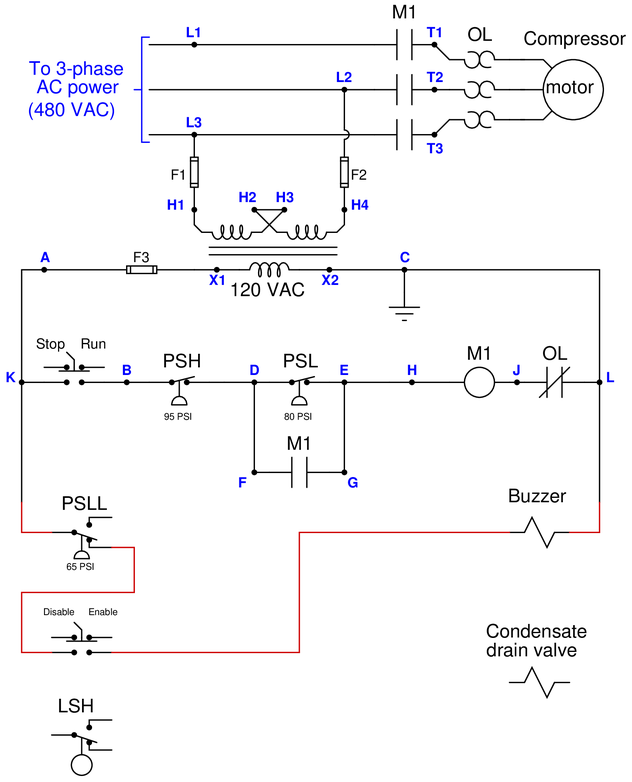
Electrically-powered air compressors are commonly used in many different industries for supplying clean, dry compressed air to machines, instrument systems, and pneumatic tools. A simple compressor system consists of a compressor which works much like a bicycle tire pump (drawing in air, then compressing it using pistons), an electric motor to turn the compressor mechanism via a V-belt, a “receiver tank” to receive the compressed air discharged by the compressor mechanism, and some miscellaneous components installed to control the pressure of the compressed air in the receiver tank and drain any condensed water vapor that enters the receiver:
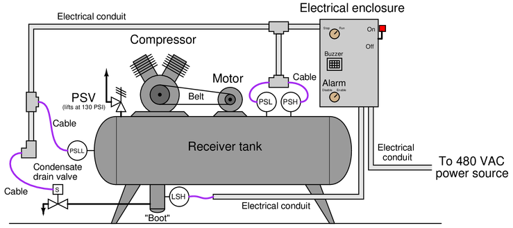
Electromechanical relay circuitry located inside the electrical enclosure decides when to turn the compressor motor on and off based on the statuses of the high- and low-pressure control switches (PSH = high pressure switch ; PSL = low pressure switch).
Your task is two-fold. First, you must figure out how to wire a new low-low pressure alarm switch (PSLL, shown on the left-hand end of the receiver) so that an alarm buzzer will activate if ever the compressed air pressure falls too low. A newly-installed hand switch located on the front panel of the electrical enclosure must be wired with this PSLL switch in such a way that the buzzer cannot energize if the hand switch is in the “alarm disable” position. Second, you must figure out how to wire a new high-level switch (LSH, shown on the “boot” of the receiver tank) so that the condensate drain valve will energize automatically to open up and drain water out of the receiver boot when the level gets too high, and then automatically shut again when the water in the boot drops down to an acceptable level.
The following schematic diagram shows the basic motor control circuit for this air compressor, with the new switches, buzzer, and drain valve shown unwired:
Complete this control circuit by sketching connecting wires between the new switches, buzzer, and drain valve solenoid. Remember that the way all switches are drawn in schematic diagrams is in their “normal” states as defined by the manufacturer: the state of minimum stimulus (when the switch is un-actuated). For pressure switches, this “normal” state occurs during a low pressure condition; for liquid level switches, this “normal” state occurs during a low-level (dry) condition. Note that each of the new process switches has SPDT contacts, allowing you to wire each one as normally-open (NO) or as normally-closed (NC) as you see fit.
Reveal answerPartial answer: (this is just one possible solution to the wiring of the pressure switch):
 Notes:
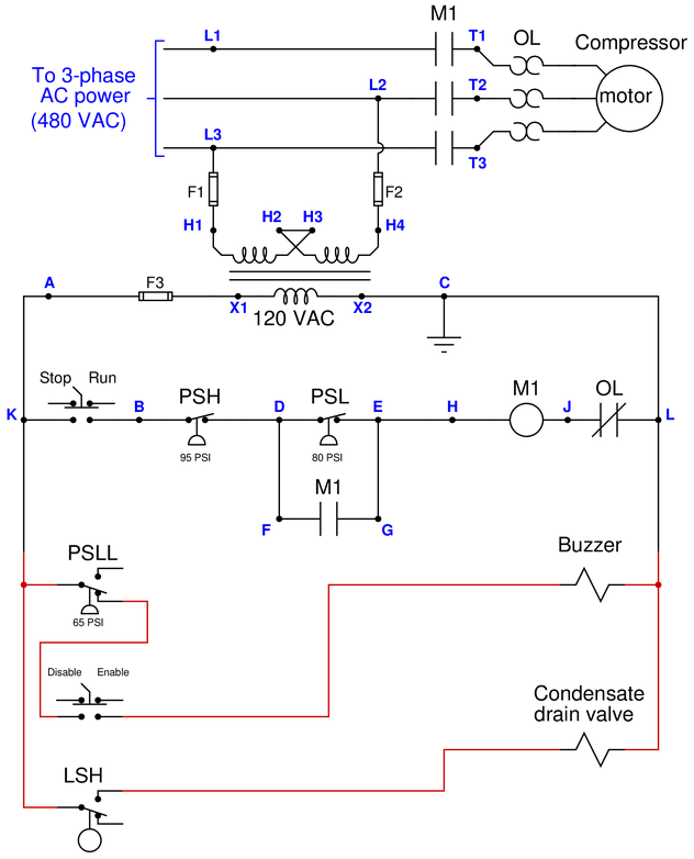
Predicting the effect of a given fault: present each of the following faults to the students, one at a time, having them comment on all the effects each fault would produce.
{\bullet} Fuse F1 blows
{\bullet} Fuse F2 blows
{\bullet} Fuse F3 blows
{\bullet} (Any) OL “heater” fails open
{\bullet} Wire H2-H3 fails open
{\bullet} PSH fails open
{\bullet} PSL fails open
{\bullet} PSLL fails open
{\bullet} LSH fails open
{\bullet} M1 seal-in contact fails open
{\bullet} M1 seal-in contact fails shorted
{\bullet} M1 coil fails open
{\bullet} M1 coil fails shortedIdentifying possible/impossible faults: suppose the compressor motor refuses to start with the Run/Stop switch in the “Run” position. Using a voltmeter, you measure 120VAC between points D and L. Present these symptoms to the students and then have them determine whether or not a series of suggested faults could account for all the symptoms, explaining why or why not for each proposed fault:
{\bullet} Fuse F1 blows
{\bullet} Fuse F2 blows
{\bullet} Fuse F3 blows
{\bullet} (Any) OL “heater” fails open
{\bullet} Wire H2-H3 fails open
{\bullet} Wire E-H fails open
{\bullet} PSH fails open
{\bullet} PSL fails open
{\bullet} PSLL fails open
{\bullet} LSH fails open
{\bullet} M1 seal-in contact fails open
{\bullet} M1 seal-in contact fails shorted
{\bullet} M1 coil fails open
{\bullet} M1 coil fails shortedDetermining the utility of given diagnostic tests: imagine the ??? fails ??? in this system (but don’t tell this to students!). Present the operator’s observation(s) to the students, have them consider possible faults and diagnostic strategies, and then propose the following diagnostic tests one by one. Have students rate the value of each test, determining whether or not each test would give us useful information (i.e. tell us something we don’t already know). Also have students describe what re
{\bullet} {\it }
{\bullet} —{\bf Yes/No}
{\bullet} —{\bf Yes/No}Diagnosing a fault based on given symptoms: imagine the ??? fails ??? in this system (but don’t tell this to students!). Present the operator’s observation(s) to the students, have them consider possible faults and diagnostic strategies, and then tell them the results of tests they propose based on the following symptoms, until they have properly identified the nature and location of the fault:
{\bullet} {\it }
{\bullet}
{\bullet} -
Question 11
Describe all that is represented by this P&ID:
 Reveal answer
This is a pressure control system for an air compressor. It uses two pressure switches, a high (“PSH”) and a low (“PSL”), sending on-off electrical signals to a logic control circuit (possibly a PLC). The logic then turns the compressor motor on and off.
A rupture disk is provided at the receiver tank for high pressure relief, and a hand-operated ball valve provides blowdown control.
The “PSHH” bubble is a high-high pressure switch, activated only when the receiver tank pressure is above normal operating pressure. It sends an on-off electrical signal to a high pressure alarm (“PAH”) indicator.
Notes:Be sure to ask your students specifically what symbols represent all the things identified in the answer!
-
Question 12
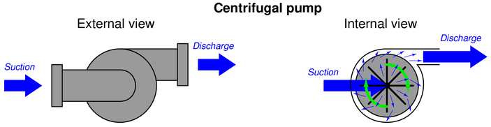
A centrifugal pump works by spinning a disk with radial vanes called an “impeller,” which flings fluid outward from the center of the disk to the edge of the disk. This kinetic energy imparted to the fluid translates to potential energy in the form of pressure when the fluid molecules strike the inner wall of the pump casing:

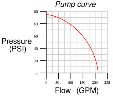
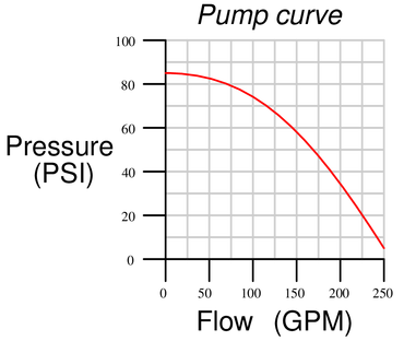
The performance of a centrifugal pump is often expressed in a special graph known as a {\it pump curve}. A typical centrifugal pump curve appears here:
Examine this pump curve, and explain in your own words what it tells us about the performance behavior of this pump.
{\bullet} One way to describe the operation of a centrifugal pump is to say it generates discharge pressure by converting kinetic energy into potential energy. Elaborate on this statement, explaining exactly where and how kinetic energy gets converted to potential energy. Hint: this might be easier to answer if you consider the “limiting case” of maximum discharge pressure described by the pump curve, where flow is zero and pressure is maximum.
{\bullet} Appealing to the conversion of energy between kinetic and potential forms, explain why discharge pressure for a centrifugal pump falls off as flow rate increases.Reveal answerA pump curve is a graph of pressure output versus liquid flow rate for a centrifugal-style pump operating at a constant rotational speed. Pump curves are essential for calculating precise pressure and flow values in liquid pumping systems.
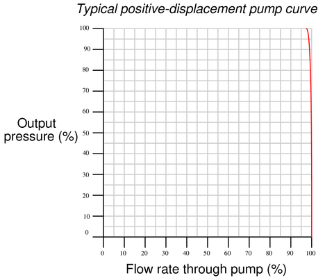
Centrifugal pumps are inertial in nature. They work by imparting kinetic energy to the fluid molecules, not by moving fixed volumes of fluid for each rotation as is the case (by definition) for a positive displacement pump. One way to envision the difference is to ask yourself whether or not fluid can flow freely through the pump mechanism by means of some external pressure source, if the pump shaft were to seize and become immobile. For a true positive displacement pump, fluid flow would become blocked: no shaft motion means fluid volume cannot pass through the pump.
A positive displacement pump spun at constant speed will pump a constant flow rate regardless of pressure. Therefore, the ideal pump curve for a positive-displacement pump is a vertical line:
The real pump curve for a positive displacement pump will bend slightly at the top (toward the left) owning to internal leakage with increasing pressure.
Notes:Prep Quiz:
A pump curve describes:
{\bullet} The proper bend radii for pipe elbows before and after a pump
{\bullet} The curvature of the flow path as fluid enters the pump casing
{\bullet} The pressure versus flow characteristics of a pump
{\bullet} The amount of fluid turbulence inside a pump at different speeds
{\bullet} The maximum density of fluid that a pump is able to handle
{\bullet} The power requirements of the pump at different fluid densities
-
Question 13
Suppose operators submitted a “trouble-call” to your instrument shop, claiming sump V-15 had an excessive liquid level inside of it (as indicated by LIR-134), and that the pump was not pumping that level down as it should:

Identify at least three possible faults, each one independently capable of accounting for the high sump level indication. Also, identify any diagnostic tests you could perform on this system to pinpoint the nature and location of the fault.
{\bullet} Suppose this trouble-call came to you during a very cold winter day, when the outside temperature was well below freezing. How might this alter the list of potential faults?
{\bullet} Explain the purpose for having check valves on the discharge lines of the two submersible sump pumps.
{\bullet} Identify some of the different pressure-measurement accessory devices visible in this P&ID.Reveal answerPossible faults include (but are not limited to):
{\bullet} Steam tracing turned off for pipe section (assuming freezing weather)
{\bullet} Clogged filter S-401
{\bullet} Shut block valve before or after filter S-401
{\bullet} Level controller LC-133 defective
{\bullet} Low-level switch LSL-133 failed
{\bullet} Nitrogen purge gas supply failed (not purging)
{\bullet} Circuit breaker to pump(s) trippedPressure gauge PI-417 could be used to tell whether or not one of pumps was running, by noting whether there was significant pressure on the common discharge line.
Notes:This question is a good candidate for a “Virtual Troubleshooting” exercise. Presenting the diagram to students, you first imagine in your own mind a particular fault in the system. Then, you present one or more symptoms of that fault (something noticeable by an operator or other user of the system). Students then propose various diagnostic tests to perform on this system to identify the nature and location of the fault, as though they were technicians trying to troubleshoot the problem. Your job is to tell them what the result(s) would be for each of the proposed diagnostic tests, documenting those results where all the students can see.
During and after the exercise, it is good to ask students follow-up questions such as:
{\bullet} What does the result of the last diagnostic test tell you about the fault?
{\bullet} Suppose the results of the last diagnostic test were different. What then would that result tell you about the fault?
{\bullet} Is the last diagnostic test the best one we could do?
{\bullet} What would be the ideal order of tests, to diagnose the problem in as few steps as possible? -
Question 14
In this oily water sump process, two submersible pumps move water out of the sump based on liquid level measurement inside the sump:
Examine this P&ID and answer the following questions:
{\bullet} Why are “check” valves installed on the discharge lines of pumps P-407 and P-408?
{\bullet} Supposing pump P-408 is the only one running, qualitatively determine the effects of pinching off the block valve immediately upstream of pressure gauge PG-419 on the following variables (e.g. increase, decrease, or remain the same):
item{\rightarrow} Pressure at the pump’s discharge port
item{\rightarrow} Pressure registered by PG-419
item{\rightarrow} Electrical current to the driving motor
item{\rightarrow} Flow rate of water through filter S-401
item{\rightarrow} Pressure registered by PG-419
item{\rightarrow} Oily water level inside the sumpReveal answer{\bullet} Why are “check” valves installed on the discharge lines of pumps P-407 and P-408? To prevent oily water from returning to the sump (from which it came) when only one pump is running.
{\bullet} Supposing pump P-408 is the only one running, qualitatively determine the effects of pinching off the block valve immediately upstream of pressure gauge PG-419 on the following variables (e.g. increase, decrease, or remain the same):
item{\rightarrow} Pressure at the pump’s discharge port (increase)
item{\rightarrow} Pressure registered by PG-419 (decrease)
item{\rightarrow} Electrical current to the driving motor (increase)
item{\rightarrow} Flow rate of water through filter S-401 (decrease)
item{\rightarrow} Pressure registered by PG-419 (remain the same)
item{\rightarrow} Oily water level inside the sump (cannot tell)The last effect (oily water sump level) is unknown because we do not know how the reduced flow of pump P-408 compares to the flow rate of water entering the sump. If the flow rate of P-408 still exceeds the input flow to the sump, the level will continue to drop although not as fast as before pinching off the block valve. If the pump’s flow rate exactly equals the influent rate, the sump level will remain constant. If the pump’s flow rate has decreased to a point where it is less than the influent flow rate, the sump level will actually rise!
-
Question 15
A level control system uses a variable-frequency motor drive (VFD) to control the speed of a pump drawing liquid out of the vessel. The greater the liquid level, the faster the pump spins, drawing liquid out at a faster rate. A low-level cutoff switch is also part of this control system, forcing the pump to a full stop to protect it from running dry if ever a low-level condition is sensed by the switch:
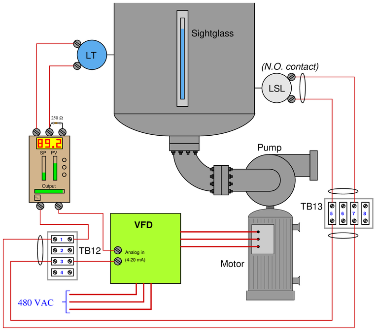
Unfortunately, this system seems to have a problem. The pump refuses to start even though the liquid level is greater than the controller’s setpoint (as indicated by both the controller and the sightglass). It was running just fine yesterday, and no technician has touched any of the components since then.
A fellow instrument technician helping you troubleshoot this problem decides to perform a simple test: he uses his multimeter (configured to measure DC current) as a “jumper” wire to momentarily short together terminals 5 and 7 on terminal strip TB13. Still, the motor remains off and does not start up as it should.
Identify the likelihood of each specified fault for this control system. Consider each fault one at a time (i.e. no coincidental faults), determining whether or not each fault could independently account for {\it all} measurements and symptoms in this system.
$$\begin{array} {|l|l|} \hline Fault & Possible & Impossible \\ \hline No~AC~power~to~VFD & & \\ \hline Controller~has~dead~4-20~mA~output & & \\ \hline Level~transmitter~out~of~calibration & & \\ \hline Level~switch~contacts~failed~shorted & & \\ \hline Level~switch~contacts~failed~open & & \\ \hline 250~ohm~resistor~failed~open & & \\ \hline Cable~between~TB12~and~TB13~failed~open & & \\ \hline Cable~between~TB13~and~LSL~failed~open & & \\ \hline \end{array}$$
Reveal answer$$\begin{array} {|l|l|} \hline Fault & Possible & Impossible \\ \hline No~AC~power~to~VFD & \surd & \\ \hline Controller~has~dead~4-20~mA~output & \surd & \\ \hline Level~transmitter~out~of~calibration & & \surd \\ \hline Level~switch~contacts~failed~shorted & & \surd \\ \hline Level~switch~contacts~failed~open & & \surd \\ \hline 250~ohm~resistor~failed~open & & \surd \\ \hline Cable~between~TB12~and~TB13~failed~open & \surd & \\ \hline Cable~between~TB13~and~LSL~failed~open & & \surd \\ \hline \end{array}$$
Notes:If the jumper test had indeed resulted in the motor starting up, it would have confirmed an open fault in either the level switch or in the cable connecting the switch to TB13. It was a very easy test to perform, and did not even require a meter (any piece of wire would have done the trick just as well).
Just because a test did not give dramatic results, does not mean it is not a good test!
Summary Quiz:
Identify the effect of a wire break at terminal 7 on TB-13:
{\bullet} The pump may become damaged from running dry
{\bullet} The controller will indicate -25
{\bullet} The controller will indicate 0
{\bullet} The motor will immediately go to full speed
{\bullet} The motor will immediately stop running
{\bullet} A fuse will blow on the 480 VAC lines
-
Question 16
How much work is done pumping 3,000 gallons of water from reservoir “A” to reservoir “B” over the hill?
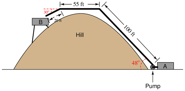
If the pump’s power output is 250 horsepower, how long will it take to pump all 3000 gallons to reservoir “B”?
{\bullet} Calculate the amount of pressure at the discharge port of the pump as it lifts water up to reservoir “B”
Reveal answerFirst, let’s determine the weight of 3,000 gallons of water:
$$\left( 3000 \hbox{ gal} \over 1 \right) \left(231 \hbox{ in}^3 \over 1 \hbox{ gal} \right) \left(1 \hbox{ ft}^3 \over 1728 \hbox{ in}^3 \right) \left(62.4 \hbox{ lb} \over \hbox{ ft}^3 \right)$$
$$25025 \hbox{ lb of water in 3000 gallons}$$
This weight of water will have to be lifted to the peak of the hill through the 100 foot pipe, but we will not use the figure of 100 feet as the displacement, since it is not vertical. Instead, we will use trigonometry to calculate the vertical lift ($x$):
$$x = (100 \hbox{ ft})(\sin 48^o)$$
$$74.31 \hbox{ ft vertical lift}$$
So, the work involved with lifting this much water to that height is:
$$W = F x \cos \theta$$
$$W = (25025 \hbox{ lb}) (74.31 \hbox{ ft}) \cos 0^o$$
$$W = 1,859,719.9 \hbox{ ft-lb of work}$$
Barring any piping friction, the horizontal section of pipe (55 ft) does not necessitate any work being done. The short, 20 foot section of downward-angled pipe, however, actually {\it releases} energy (performs negative work) because it lets the water drop in height. This drop is:
$$\hbox{drop} = (20 \hbox{ ft})(\sin 30^o) = 10 \hbox{ ft}$$
Since the same amount of water will drop this amount, the negative work done here is:
$$W = F x \cos \theta$$
$$W = (25025 \hbox{ lb}) (10 \hbox{ ft}) \cos 180^o$$
$$W = -250,250 \hbox{ ft-lb of work}$$
The total (net) work done, then, is the sum of these two figures:
$$W_{net} = 1,859,719.9 \hbox{ ft-lb} - 250,250 \hbox{ ft-lb}$$
$$1,609,469.9 \hbox{ ft-lb of work}$$
At a pump power output of 250 HP (137,500 ft-lb per second)
$$t = {W \over P}$$
$$t = {1609469.9 \hbox{ ft-lb} \over 137500 \hbox{ ft-lb/s}} = 11.71 \hbox{ seconds}$$
-
Question 17
One laborer working on the top of a building uses a manual hoist to lift 10 gallons of water 30 feet up from ground level, while a second laborer uses an electric pump to do the same:
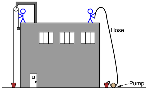
First, calculate the amount of work needed to lift 10 gallons up to the same roof. Then, calculate the time required for the pump to do this job, assuming a rating of 1.5 horsepower.
Reveal answerCalculating the work in raising 10 gallons of water 30 feet up:
$$\left( 10 \hbox{ gal} \over 1 \right) \left(231 \hbox{ in}^3 \over 1 \hbox{ gal} \right) \left(1 \hbox{ ft}^3 \over 1728 \hbox{ in}^3 \right) \left(62.4 \hbox{ lb} \over \hbox{ ft}^3 \right)$$
$$83.42 \hbox{ lb of water in 10 gallons}$$
Now, knowing both the force (83.42 lb) and the displacement (30 ft), we may calculate the work done:
$$W = F x \cos \theta$$
$$W = (83.42 \hbox{ lb})(30 \hbox{ ft})(\cos 0^o)$$
$$2502.5 \hbox{ ft-lb of work}$$
Now, since we know that 1 horsepower is 550 ft-lbs of work {\it per second of time}, we may take this total amount of work (2502.5 ft-lb) and divide by the pump’s power in foot-pounds per second to arrive at an answer for time in seconds. Since we know the pump’s power rating is 1.5 horsepower, it means it is capable of doing 825 ft-lb of work per second:
$$t = {W \over P} = {2502.5 \hbox{ ft-lb} \over 825 \hbox{ ft-lb/s}}$$
$$t = 3.033 \hbox{ seconds}$$
-
Question 18
A surface-mounted water pump pulls water out of a well by creating a vacuum, though it might be more technically accurate to say that the pump works by reducing pressure in the inlet pipe to a level less than atmospheric pressure, allowing atmospheric pressure to then push water from the well up the pump’s inlet pipe:
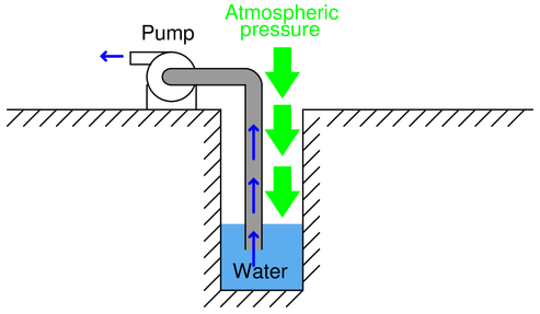
Based on this description of pump operation, what is the theoretical maximum height that any pump can lift water out of a well, assuming the well is located at sea level?
Water wells located at altitudes other than sea level will have different theoretical maximum lifting heights (i.e. the farthest distance a surface-mounted pump may suck water out of the well). Research the average barometric pressure in Denver, Colorado (the “mile-high” city) and determine how far up a surface pump may draw water from a well in Denver.
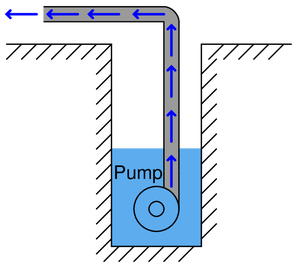
Domestic water wells may be hundreds of feet deep. How can water be pumped out of wells this deep, given the height limitation of vacuum pumping?
{\bullet} If the liquid in question was something other than water, would the maximum “lift” depth be different? Why or why not?
Reveal answer406.9 inches, which is a little bit less than 34 feet. For this amount of “lift height,” the pump would have to create a near-perfect vacuum in the inlet pipe. To calculate this figure, convert 14.7 PSIA into inches of water column absolute (14.7 PSIA)(27.68 “W.C. / PSI).
Since this kind of water pump works by creating a vacuum (reducing the inlet pressure to something less than 14.7 PSIA), it is inherently limited in lift height. Since atmospheric pressure is always 14.7 PSIA (on Earth, anyway), this kind of pump simply cannot suck water any higher than this amount of pressure expressed in inches or feet of water.
The average barometric pressure in Denver is 24.63 inches of mercury absolute (12.097 PSIA). This equates to a water-lifting height of 334.9 inches, or 27.9 feet.
Submersible pumps overcome this limit by creating a positive pressure rather than a vacuum. The pumping action is therefore not limited by the relatively low pressure of Earth’s atmosphere, but only by the capacity and design of the pump itself:
-
Question 19
Examine this P&ID:

Each pump is of the “reciprocating” type, a form of positive displacement machine. In essence, each rotation of the motor shaft causes the pump to move a measured quantity of liquid from its inlet to its outlet.
What will happen to the liquid level inside the vessel over time if one pump is moving more liquid flow?
Would you characterize this process as inherently self-regulating or inherently integrating?
Reveal answerThe liquid level inside the vessel will drift either up or down (depending on which pump moves more liquid) at a rate determined by the differential liquid flow ($Q_{in}$ $-$ $Q_{out}$). This makes it an integrating process.
Integrating processes are characterized by the capacity to experience persistent mass and/or energy imbalances, where the out-flow of mass and/or energy does not naturally reach equilibrium the in-flow over time. Self-regulating processes, by contrast, naturally equalize their mass and energy balances as the process variable changes.
-
Question 20
Suppose two identical pumps exhibit the exact same pump curve shown below:
If these two pumps are connected in series with a suction pressure of 45 PSI ($P_1$ = 45 PSI), calculate pressures $P_2$ and $P_3$ as well as total discharge flow rate when the flow rate through each pump is 150 GPM:
If these two pumps are connected in parallel with a suction pressure of 45 PSI ($P_1$ = 45 PSI), calculate pressures $P_2$ and $P_3$ as well as total discharge flow rate when the flow rate through each pump is 150 GPM:
{\bullet} Explain how series and parallel pumps act much the same as series and parallel electrical sources.
{\bullet} Where might an engineer choose to use series pumps versus parallel pumps in a piping system?Reveal answerAccording to the pump curve, the pressure will be 60 PSI at a flow rate of 150 GPM. This means each pump boosts its suction pressure by 60 PSI at the discharge.
In the series configuration, this means $P_2 = P_1 + 60$ and $P_3 = P_2 + 60$. Therefore, $P_2$ = 105 PSI and $P_3$ = 165 PSI. Total flow will be 150 GPM.
In the parallel configuration, this means $P_2 = P_1 + 60$ and $P_3 = P_1 + 60$. Therefore, $P_2$ = $P_3$ = 105 PSI. Total flow will be 300 GPM.
-
Question 21
Given the following pump curve for a water pump driven at a constant speed by an AC induction motor, determine the maximum flow rate of water it can deliver to different heights above the pump’s discharge port:
{\bullet} Maximum flow at 10 feet above pump level =
{\bullet} Maximum flow at 50 feet above pump level =
{\bullet} Maximum flow at 100 feet above pump level =
{\bullet} Maximum flow at 150 feet above pump level =
Reveal answerUse the Control.com pressure calculator to convert the inches above the pump (“WC) to PSI and compare that PSI to the flow from the graph.
Reading values from a chart will always provide an approximate value.
{\bullet} Maximum flow at 10 feet above pump level $\approx$ 250 GPM
{\bullet} Maximum flow at 50 feet above pump level $\approx$ 225 GPM
{\bullet} Maximum flow at 100 feet above pump level $\approx$ 185 GPM
{\bullet} Maximum flow at 150 feet above pump level $\approx$ 135 GPM
-
Question 22
Sketch the pump curve for a positive-displacement pump turned at a constant speed by an electric motor:
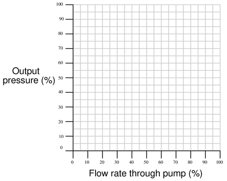
{\bullet} What will change about the pump curve graph if the driving motor’s speed changes?
Reveal answerThe ideal pump curve for a positive-displacement pump is a vertical line, but due to internal leakage the real pump curve looks something more like this:
-
Question 23
An alternative to using a pressure-relief valve to control pressure in a hydraulic system is to use a variable-displacement pump with hydraulic feedback:

As hydraulic pressure increases, the pump mechanism automatically adjusts to give less volume displacement per rotation. Explain how this works to regulate pressure, and also why it saves energy compared to the more traditional design of a constant-displacement pump combined with a pressure-relief valve.
Reveal answerInstead of wasting unused hydraulic energy in a pressure relief valve, this system reduces the amount of hydraulic energy input to the system when it is not needed.
Follow-up question: a common design of variable-displacement hydraulic pump (and motor!) is the swash plate style, where the angle of the swash plate changes to alter the pump’s per-revolution displacement. Research this pump design and explain how it works.
-
Question 24
Hydraulic (liquid) power systems require pressure regulation just like pneumatic (air) power systems. However, pressure control must be done differently in a hydraulic system. In a pneumatic system, the electric motor driving the air compressor is simply turned on and off to maintain air system pressure between two setpoints. In a hydraulic system, the electric motor driving the positive-displacement pump continually runs, with a pressure relief valve regulating line pressure:
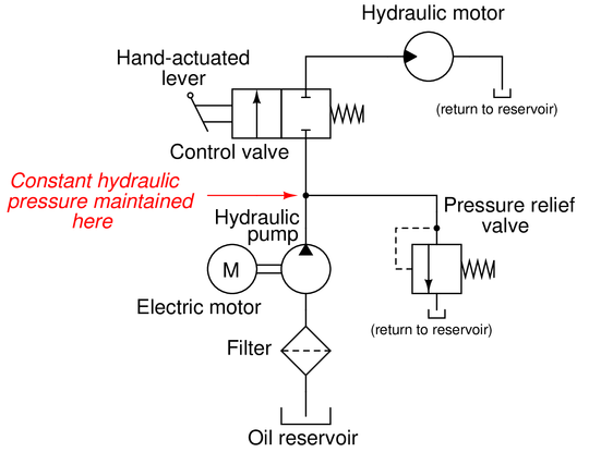
If not for the pressure-relief valve, the hydraulic pump would “lock up” and refuse to turn whenever the control valve was placed in the “stop” position (as shown in the diagram). With the pressure-relief valve in place, the pump will continue to spin and hydraulic pressure will be maintained.
Explain why a positive-displacement hydraulic pump will “lock up” if its outlet line is blocked, and explain the operating principle of the pressure-relief valve.
{\bullet} Identify what would have to be altered in this fluid power system to reverse the direction of the motor.
{\bullet} Would this system function adequately if the pressure relief valve were relocated to a location “downstream” of the spool valve?
{\bullet} If the filter were to entirely plug and prevent flow through it, would the hydraulic pump “lock up” in the same way it would having its discharge port blocked?
{\bullet} The Law of Energy Conservation states that energy cannot be created or destroyed, but must be accounted for in every system. When the spool valve is left in the “off” position and the motor does not move, where does all the energy go that is input by the pump into the fluid system? For example, if the hydraulic pump is being spun by a 1-horsepower motor, what happens to all that power if it is not directed to the motor to do mechanical work?Reveal answerA vitally important concept to grasp here is that of incompressibility. Air is a compressible fluid, but hydraulic oil is incompressible for all practical purposes. Thus, a positive-displacement pump mechanism will lock up if the incompressible fluid has no place to exit.
Notes:The purpose of the pressure relief valve is to open up when the pressure achieves the setpoint value, thus controlling pressure by sending a measured flow of hydraulic fluid back to the reservoir.
-
Question 25
A centrifugal pump works by spinning a disk with radial vanes called an “impeller,” which flings fluid outward from the center of the disk to the edge of the disk. This kinetic energy imparted to the fluid translates to potential energy in the form of pressure when the fluid molecules strike the inner wall of the pump casing:
The energy conveyed by the liquid exiting the discharge port of this pump comes in two forms: pressure head and velocity head. Ignoring differences in elevation (height), we may apply Bernoulli’s equation to describe this fluid energy:
$$\hbox{Fluid Energy at discharge port} = {\rho v^2 \over 2} + P$$
Where,
Fluid Energy = expressed in units of pounds per square foot, or PSF
$P$ = Gauge pressure (pounds per square foot, or PSF)
$\rho$ = Mass density of fluid (slugs per cubic foot)
$v$ = Velocity of fluid (feet per second)
When the discharge port is completely blocked by an obstruction such as a closed valve or a blind, there is no velocity at the port ($v = 0$) and therefore the total energy is in the potential form of pressure ($P$). When the discharge port is completely unobstructed, there will be no pressure at the port ($P = 0$) and therefore the total energy is in kinetic form (${\rho v^2 \over 2}$). During normal operation when the discharge experiences some degree of resistance, the discharge fluid stream will possess some velocity as well as some pressure.
Assuming that the fluid molecules’ maximum velocity is equal to the speed of the impeller’s rim, calculate the discharge pressure under these conditions for a pump having an 8 inch diameter impeller spinning at 1760 RPM and a discharge port of 2 inches diameter, with water as the fluid (mass density $\rho$ = 1.951 slugs per cubic foot) and assuming atmospheric pressure at the suction port:
{\bullet} Discharge flow = 0 GPM ; $P$ =
{\bullet} Discharge flow = 100 GPM ; $P$ =
{\bullet} Discharge flow = 200 GPM ; $P$ =
{\bullet} Discharge flow = 300 GPM ; $P$ =
{\bullet} Discharge flow = 400 GPM ; $P$ =
{\bullet} Discharge flow = 500 GPM ; $P$ =
Next, calculate the maximum flow rate out of the pump with a completely open discharge port ($P = 0$).
Reveal answerThe velocity of the fluid molecules will be equal to the rim speed of the impeller, which is the circumference of the impeller multiplied by its rotational speed:
$$\left({1760 \hbox{ rev} \over \hbox{min}}\right) \left({8 \pi \hbox{ in} \over \hbox{rev}}\right) = 44233.6 \hbox{ in/min} = 61.436 \hbox{ ft/s}$$
This velocity lets us calculate the velocity head at the impeller’s rim. If we assume the water enters the pump with no pressure, this velocity head should be the only energy the water possesses at the impeller rim:
$$\hbox{Fluid Energy at impeller rim} = {\rho v^2 \over 2} = {(1.951)(61.436)^2 \over 2} = 3681.9 \hbox{ PSF} = 25.57 \hbox{ PSI}$$
This figure of 25.57 PSI will be the blocked-discharge pressure, with 0 GPM of exit flow rate.
Conversely, if we imagine a situation where the discharge port is completely unblocked to achieve zero discharge pressure, the fluid velocity exiting the port will be approximately equal to the impeller rim velocity. Applying this velocity to the Continuity equation to calculate volumetric flow at the 2-inch diameter discharge port:
$$Q = Av$$
$$Q = \pi r^2 v$$
$$Q = (\pi)(1^2)(44233.6) = 138964 \hbox{ in}^3\hbox{/min} = 601.6 \hbox{ GPM}$$
Therefore, the maximum flow rate of this pump at zero discharge pressure will be approximately 600 gallons per minute.
At any flow rate between zero and maximum, the combined sum of velocity and pressure heads at the pump discharge must be equal to the maximum head at the impeller rim (3681.9 PSF equivalent). Therefore:
$$3681.9 = {\rho v^2 \over 2} + P$$
$$P = 3681.9 - {\rho v^2 \over 2}$$
Using the Continuity equation to calculate discharge velocity at 100 GPM (23100 in$^{3}$/min), and then Bernoulli’s equation to calculate discharge pressure:
$$v = {Q \over A} = {23100 \over \pi} = 7352.96 \hbox{ in/min} = 10.21 \hbox{ ft/s}$$
$$P = 3681.9 - {(1.951) (10.21^2) \over 2} = 3580.1 \hbox{ PSF} = 24.86 \hbox{ PSI}$$
Using the Continuity equation to calculate discharge velocity at 200 GPM (46200 in$^{3}$/min), and then Bernoulli’s equation to calculate discharge pressure:
$$v = {Q \over A} = {46200 \over \pi} = 14705.9 \hbox{ in/min} = 20.42 \hbox{ ft/s}$$
$$P = 3681.9 - {(1.951) (20.42^2) \over 2} = 3274.9 \hbox{ PSF} = 22.74 \hbox{ PSI}$$
Using the Continuity equation to calculate discharge velocity at 300 GPM (69300 in$^{3}$/min), and then Bernoulli’s equation to calculate discharge pressure:
$$v = {Q \over A} = {69300 \over \pi} = 22058.9 \hbox{ in/min} = 30.64 \hbox{ ft/s}$$
$$P = 3681.9 - {(1.951) (30.64^2) \over 2} = 2766.2 \hbox{ PSF} = 19.21 \hbox{ PSI}$$
Using the Continuity equation to calculate discharge velocity at 400 GPM (92400 in$^{3}$/min), and then Bernoulli’s equation to calculate discharge pressure:
$$v = {Q \over A} = {92400 \over \pi} = 29411.8 \hbox{ in/min} = 40.85 \hbox{ ft/s}$$
$$P = 3681.9 - {(1.951) (40.85^2) \over 2} = 2054.04 \hbox{ PSF} = 14.26 \hbox{ PSI}$$
Using the Continuity equation to calculate discharge velocity at 500 GPM (115500 in$^{3}$/min), and then Bernoulli’s equation to calculate discharge pressure:
$$v = {Q \over A} = {115500 \over \pi} = 36764.8 \hbox{ in/min} = 51.06 \hbox{ ft/s}$$
$$P = 3681.9 - {(1.951) (51.06^2) \over 2} = 1138.4 \hbox{ PSF} = 7.905 \hbox{ PSI}$$
Summarizing these calculated results:
{\bullet} Discharge flow = 0 GPM ; $P$ = 25.57 PSI
{\bullet} Discharge flow = 100 GPM ; $P$ = 24.86 PSI
{\bullet} Discharge flow = 200 GPM ; $P$ = 22.74 PSI
{\bullet} Discharge flow = 300 GPM ; $P$ = 19.21 PSI
{\bullet} Discharge flow = 400 GPM ; $P$ = 14.26 PSI
{\bullet} Discharge flow = 500 GPM ; $P$ = 7.91 PSI
If we were to plot these flow and pressure data points, we would have a pump curve for this centrifugal pump.
-
Question 26
Calculate the volumetric flow rate (in units of cubic feet per minute) for water flowing out of the 10-inch diameter discharge pipe of a centrifugal pump at a velocity of 25 feet per second. Then, convert that flow rate into units of gallons per minute.
Reveal answerCross-sectional area of the pipe in square feet:
$$area= \pi \cdot r^2$$
$$area=\pi \cdot (5~in)^2$$
$$area = 78.5~in^2$$
$$area = 78.5~in^2 \cdot {1~ft^2 \over 144~in^2}$$
$$area = 0.545~ft^2$$
Flow rate in cubic feet per second:
$$Q = area \cdot velocity$$
$$Q = 0.545~ft^2 \cdot 25 {ft \over sec}$$
$$Q = 13.625 {ft^3 \over sec}$$
Convert to cubic feet per minute:
$$Q = 13.625 {ft^3 \over sec} \cdot {60~sec \over 1~min}$$
$Q$ = 817.5 ft$^{3}$/min
Convert CFM to GPM
$$817.5~CFM \cdot {7.48~GPM \over 1~CFM}$$
$Q$ = 6114.9 GPM
Notes:Here, I am assuming an inside pipe diameter of exactly 10.00 inches.

