Facebook
 Google
 GitHub
 Linkedin
Instrumentation and Process Control
Solenoid Controlled Systems
-
Question 1
A burner management system (BMS) monitors the status of the flame at the base of this incinerator, to ensure fuel gas does not keep entering the combustion chamber unless there is an established fire to burn it:

Explain the purpose of solenoid valve SV-115, identifying whether it is normally energized (NE) or normally de-energized (NDE).
Also, explain the purposes of SV-111, SV-112, and SV-113 in this incinerator control system.
Reveal answerSolenoid SV-115 vents all actuating air pressure from flow control valve FV-38 whenever its coil is de-energized. Thus, SV-115 is “normally energized” to maintain actuating air pressure to FV-38.
Solenoids SV-111, SV-112, and SV-113 act to prevent fuel gas from reaching the incinerator’s burner assembly when the Burner Management System (BMS) sends a trip signal. SV-111 and SV-112 are block valves, while SV-113 is a bleed (“vent”) valve, making this a “double-block and bleed” valve arrangement. A similar solenoid valve arrangement can be seen on the pilot burner gas line with solenoids SV-101, SV-102, and SV-103.
-
Question 2
Solenoid valve SV-92 plays an important role in this compressor inlet separator control system. Level control valve LV-92 opens up when needed to drain liquid out of the “boot” of the separator vessel, which ideally contains only gas (vapor). Examine this P\&ID and then answer the following questions:

{\bullet} Identify the statuses of SV-92 and LV-92 when the separator boot liquid level is at or below the normal level of 1 foot 4 inches.
{\bullet} Describe how this system responds to high liquid levels in the separator boot.
{\bullet} What will be the consequence of an instrument air supply failure, as it relates to the separator boot liquid level?
{\bullet} What will be the consequence of an AC power failure to LIC-92?
Reveal answer{\bullet} Identify the statuses of SV-92 and LV-92 when the separator boot liquid level is at or below the normal level of 1 foot 4 inches.
LV-92 will be closed, and SV-92’s coil will be de-energized.
{\bullet} Describe how this system responds to high liquid levels in the separator boot.
If LT-92 senses a high liquid level, controller LIC-92 will respond by applying electrical power to SV-92. When SV-92 actuates, it sends instrument air to the diaphragm actuator of LV-92 to cause that drain valve to open. As LV-92 drains liquid out of the boot, the level sensed by LT-92 decreases over time, eventually to a point where controller LIC-92 stops sending power to the coil of SV-92.
{\bullet} What will be the consequence of an instrument air supply failure, as it relates to the separator boot liquid level?
Without instrument air supply (IAS), the level drain valve LV-92 can never open and the separator boot liquid level will rise unabated. Eventually LSHH-231 will detect the high-high level condition and command the Emergency Shut-Down (ESD) system to turn the compressor off in order to avoid damaging that machine.
{\bullet} What will be the consequence of an AC power failure to LIC-92?
Without AC power to energized the coil of solenoid SV-92, the level drain valve LV-92 will never be commanded to open by SV-92 and the separator boot liquid level will rise unabated. Eventually LSHH-231 will detect the high-high level condition and command the Emergency Shut-Down (ESD) system to turn the compressor off in order to avoid damaging that machine.
-
Question 3
This loop sheet shows a pneumatic reactor temperature control system utilizing a solenoid valve to assist in the actuation of process valve TV-135:
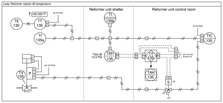
Determine the following, based on a close inspection and analysis of the diagram:
{\bullet} The typical status of the output switch contact on TY-135 (NO or NC)
{\bullet} The effect of an AC power loss from breaker #4
{\bullet} The effect of the solenoid vent becoming plugged or accidentally capped by a technician
Reveal answer{\bullet} The typical status of the output switch contact on TY-135 (NO or NC)
TY-135’s output must typically be conducting (switch contacts closed) in order to pass AC power on to the coil of the solenoid valve and maintain its “normally energized” status.
{\bullet} The effect of an AC power loss from breaker #4
The solenoid coil would de-energized, venting air pressure from the input of TV-135 and causing that process valve to go to its “fail” (closed) position.
{\bullet} The effect of the solenoid vent becoming plugged or accidentally capped by a technician
If ever the discrete controller TY-135 commands the solenoid valve to trip, it would force TV-135 to hold its position rather than close as it should.
-
Question 4
Determine the “normal energization” states (e.g. NE or NDE) of each solenoid valve in this diagram, assuming the process valve needs to be closed when the process is running as it should:
Also, determine whether one or both solenoids need to “trip” in order to make the process valve go to its fail-state. In other words, is this a 1oo2 to trip system, or a 2oo2 to trip system?
(Again, those above are the abbreviations for ‘one out of two’ and ‘two out of two’)
Suppose the ball valve refused to shut off when it should. Identify at least two possible faults that could cause this to happen.
{\bullet} Suppose the probability of each solenoid valve “sticking” in its regular operating position instead of tripping when commanded is $4.5 \times 10^{-3}$. Calculate the probability of the process valve refusing to trip when commanded as a result of this type of failure.
{\bullet} Suppose the probability of each solenoid valve “sticking” in its tripped position instead of going to its regular operating position when commanded is $3.7 \times 10^{-3}$. Calculate the probability of the process valve refusing to go to its regular operating position when commanded as a result of this type of failure.
{\bullet} Suppose the probability of each solenoid valve accidentally tripping during regular operation is $9.5 \times 10^{-4}$. Calculate the probability of the process valve tripping accidentally as a result of this type of failure.Reveal answerEither solenoid valve tripping is sufficient to “fail” the process valve (i.e. 1oo2 to trip):
Possible faults:
{\bullet} Wiring failed open to either solenoid coil
{\bullet} Instrument air supply dead
{\bullet} Break in tubing between solenoid valves
{\bullet} Break in tubing between upper solenoid valve and ball valve actuator
{\bullet} Large leak in ball valve actuatorNotes:This question is a good candidate for a “Virtual Trip-testing” exercise. Presenting the diagram to students, you pose an assignment whereby students must figure out how to test some component of this system to check that it will operate as intended to shut down the system in an abnormal (trip) condition, with some realistic limitation (e.g. power cannot be shut off to the load). Students then propose various methods for executing the test. Your job is to determine whether or not their proposed tests will achieve the desired result(s).
During and after the exercise, it is good to ask students follow-up questions such as:
{\bullet} Where might our planned test strategy go wrong? In other words, what thing(s) might happen to foil our test, either to invalidate the results or to not honor the stated limitation(s)?
{\bullet} Suppose the limitation were different. How would this affect our ability to carry out the test?
{\bullet} Is the last test strategy best one we could execute? -
Question 5
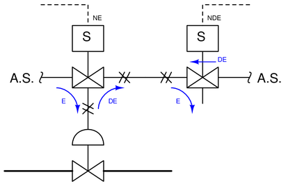
Sketch arrows next to each of the two solenoid valves showing the directions of air flow in the energized (E) and de-energized (D) states, assuming both of the solenoid valves must “trip” in order to force the process valve to go to its “fail” position (i.e. 2oo2 to trip):

-
Question 6
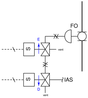
Sketch arrows next to each of the two solenoid valves showing the directions of air flow in the energized (E) and de-energized (D) states, assuming the process control valve is supposed to be open in regular operation and close if both of the solenoid valves “trip” (i.e. 2oo2 to trip):
 Reveal answer
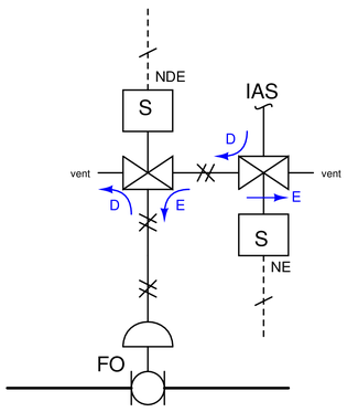 Notes:
This question is a good candidate for a “Virtual Trip-testing” exercise. Presenting the diagram to students, you pose an assignment whereby students must figure out how to test some component of this system to check that it will operate as intended to shut down the system in an abnormal (trip) condition, with some realistic limitation (e.g. power cannot be shut off to the load). Students then propose various methods for executing the test. Your job is to determine whether or not their proposed tests will achieve the desired result(s).
During and after the exercise, it is good to ask students follow-up questions such as:
{\bullet} Where might our planned test strategy go wrong? In other words, what thing(s) might happen to foil our test, either to invalidate the results or to not honor the stated limitation(s)?
{\bullet} Suppose the limitation were different. How would this affect our ability to carry out the test?
{\bullet} Is the last test strategy best one we could execute? -
Question 7
This fluid diagram shows the components and connections of a Bettis self-contained hydraulic module used to automatically shut off a “line valve” on a natural gas pipeline in the event of the pipeline pressure going outside of its limits (either falling below the low-pressure limit or rising above the high-pressure limit):
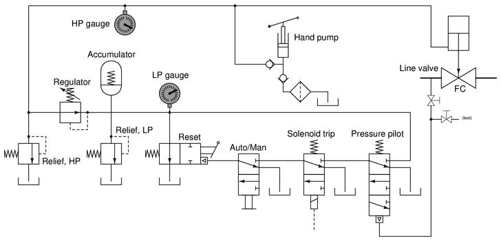
Identify all spool valve positions, and also trace the direction of oil flow, following a solenoid “trip” event.
Reveal answer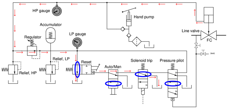 Notes:
This question is a good candidate for a “Virtual Trip-testing” exercise. Presenting the diagram to students, you pose an assignment whereby students must figure out how to test some component of this system to check that it will operate as intended to shut down the system in an abnormal (trip) condition, with some realistic limitation (e.g. power cannot be shut off to the load). Students then propose various methods for executing the test. Your job is to determine whether or not their proposed tests will achieve the desired result(s).
During and after the exercise, it is good to ask students follow-up questions such as:
{\bullet} Where might our planned test strategy go wrong? In other words, what thing(s) might happen to foil our test, either to invalidate the results or to not honor the stated limitation(s)?
{\bullet} Suppose the limitation were different. How would this affect our ability to carry out the test?
{\bullet} Is the last test strategy best one we could execute? -
Question 8
Suppose this valve control system has a problem. The control valve (LV-104) does not move to the full-open position as it should when the solenoid is de-energized, although it will move when the 4-20 mA current signal to the I/P transducer is varied while the solenoid is energized:
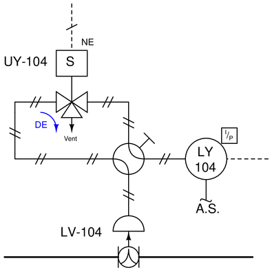
Identify the likelihood of each specified fault for this circuit. Consider each fault one at a time (i.e. no coincidental faults), determining whether or not each fault could independently account for {\it all} measurements and symptoms in this circuit.
$$\begin{array} {|l|l|} \hline Fault & Possible & Impossible \\ \hline Manual~valve~in~“bypass”~position & & \\ \hline Solenoid~coil~failed~open & & \\ \hline Solenoid~coil~failed~shorted & & \\ \hline Solenoid~valve~(UY-104)~spool~stuck & & \\ \hline Solenoid~valve~(UY-104)~vent~plugged & & \\ \hline Air~supply~to~LY-104~failed & & \\ \hline Signal~wiring~to~LY-104~failed~open & & \\ \hline Signal~wiring~to~LY-104~failed~shorted & & \\ \hline Control~valve~(LV-104)~stuck & & \\ \hline \end{array}$$
Reveal answer$$\begin{array} {|l|l|} \hline Fault & Possible & Impossible \\ \hline Manual~valve~in~“bypass”~position & \surd & \\ \hline Solenoid~coil~failed~open & & \surd \\ \hline Solenoid~coil~failed~shorted & & \surd \\ \hline Solenoid~valve~(UY-104)~spool~stuck & \surd & \\ \hline Solenoid~valve~(UY-104)~vent~plugged & \surd & \\ \hline Air~supply~to~LY-104~failed & & \surd \\ \hline Signal~wiring~to~LY-104~failed~open & & \surd \\ \hline Signal~wiring~to~LY-104~failed~shorted & & \surd \\ \hline Control~valve~(LV-104)~stuck & & \surd \\ \hline \end{array}$$
Notes:This question is a good candidate for a “Virtual Trip-testing” exercise. Presenting the diagram to students, you pose an assignment whereby students must figure out how to test some component of this system to check that it will operate as intended to shut down the system in an abnormal (trip) condition, with some realistic limitation (e.g. power cannot be shut off to the load). Students then propose various methods for executing the test. Your job is to determine whether or not their proposed tests will achieve the desired result(s).
During and after the exercise, it is good to ask students follow-up questions such as:
{\bullet} Where might our planned test strategy go wrong? In other words, what thing(s) might happen to foil our test, either to invalidate the results or to not honor the stated limitation(s)?
{\bullet} Suppose the limitation were different. How would this affect our ability to carry out the test?
{\bullet} Is the last test strategy best one we could execute?