 Facebook
 Google
 GitHub
 Linkedin
Electricity and Electronics
Three Phase AC Circuits
-
Question 1
Suppose you need to design a three-phase electric heater to dissipate 15 kW of heat when powered by 480 VAC. Your options are to build a delta-connected heater array or a wye-connected heater array:

Calculate the proper resistance value for each array, to achieve the desired heat output:
$R_{delta}$ =
$R_{wye}$ =
Reveal answerPerhaps the simplest approach to this problem is to calculate the power dissipation of each resistor inside of each three-resistor array. Since power is a scalar quantity (i.e. it adds directly, not trigonometrically), the 15 kW total heat output of each array means each resistor inside of each array must dissipate 5 kW of power.
In the delta-connected heater, each resistor sees full line voltage (480 VAC), therefore the resistance may be calculated as such:
$$R = {V^2 \over P} = {480^2 \over 5000} = 46.08~\Omega$$
In the wye-connected heater, each resistor sees $1 \over \sqrt{3}$ of the full line voltage (480 VAC), which is 277.1 VAC. Therefore the resistance may be calculated as such:
$$R = {V^2 \over P} = {277.1^2 \over 5000} = 15.36~\Omega$$
-
Question 2
A three-phase electric motor operating at a line voltage of 4160 VAC (RMS) draws 27.5 A of current (RMS) through each of its lines. Calculate the amount of apparent power consumed by this motor in both kVA electrical and HP mechanical units.
Reveal answerApparent power is the product of the voltage and current, as with any standard electrical power calculation, and also multiplied by $\sqrt{3}$
$$S=V \cdot I \cdot \sqrt{3}$$
$S$ = 198.15 kVA
Converting from VA to HP divides the total VA by 746 (watts per HP).
$$P_{mech} = {S \over 746}$$
$P_{mech}$ = 265.6 HP
-
Question 3
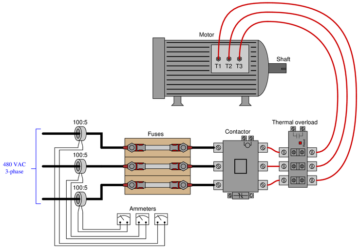
Suppose the current through each of the ammeters is 2.81 amps, and the ratio of each current transformer is 100:5. Calculate the horsepower output of this AC motor, assuming a power factor of 1 and an efficiency of 88%
$P$ =
Reveal answerWith 100:5 ratios at each CT, the line current to this motor is twenty times the amount of current through each ammeter:
$$(2.81) \left({100 \over 5}\right) = 56.2 ~A$$
At a line voltage of 480 VAC and a line current of 56.2 amps, the total electrical power in this 3-phase system may be calculated as follows:
$$P_{total} = (\sqrt{3}) (I_{line}) (V_{line})$$
$$P_{total} = (\sqrt{3}) (56.2) (480) = 46.724~kW$$
At an efficiency of 88%, the total power would be reduced from this theoretical maximum.
$$P_{actual}=P_{total} \cdot 0.88$$
$P_{actual}=41.117~kW$
Since we know there are 746 watts to every horsepower, we may convert this kW figure into HP as follows:
$$41.117~kW=41117~W$$
$$\left({41117~W \over 1}\right) \left({1~HP \over 746~W}\right) = 55.12~HP$$
-
Question 4
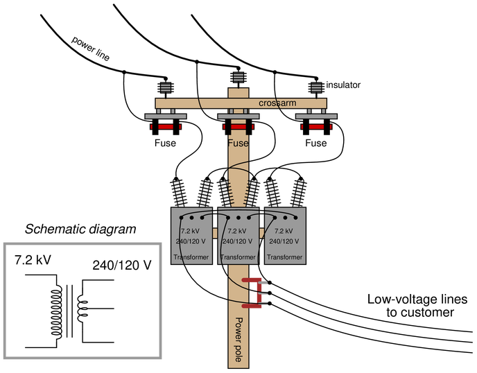
Examine the primary and secondary connections on this three-phase transformer bank, and then determine the line voltage to the customer, assuming 12.5 kV line voltage on the distribution power lines. The schematic diagram shown in the grey box is typical for each of the three transformers:
 Reveal answer
The transformer primary windings are connected in a Wye configuration, which means each primary winding receives the 7.2 kV phase voltage. The secondary windings are connected in a Delta configuration, making the secondary line voltage equal to 240 volts.

-
Question 5
Three step-down transformers have their primary (high-voltage) terminals connected together in a “wye” configuration so that the 12.5 kV line voltage energizes each primary winding with 7.2 kV. The secondary terminals on each transformer have been left disconnected:
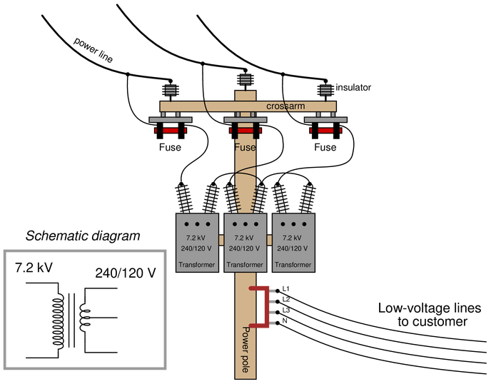
Sketch proper wire connections to provide 120/208 VAC to the customer.
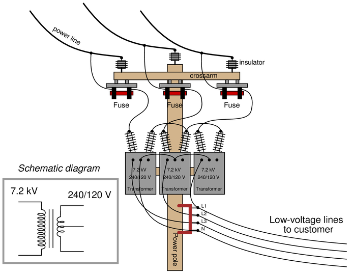
Reveal answerWhat we need here is a “wye” configuration on the secondary windings of the three transformers, using the center-tap of each to get 120 VAC at each phase. The pictorial diagram shown here is one possible solution, but not the only one:
-
Question 6
Calculate the operating current through each of the load resistances shown in this circuit (assuming each three-phase load is balanced):

Also, calculate the power dissipated by each load.
Reveal answerIn the direct-connected load on the left, each 1240 Ω resistor sees $1 \over \sqrt{3}$ of the 13.8 kV line voltage (7967.4 volts), therefore, each resistor current is equal to:
$$I = {V \over R} = {7967.4 \over 1240} = 6.425 \hbox{ amps}$$
Since each resistor sees 7967.4 volts and carries 6.425 amps, the power for each resistor will be:
$$P = IV = (6.425)(7967.4) = 51.194 \hbox{ kW}$$
The power for this load is simply the power of all resistors combined:
$$P_{total} = 153.58 \hbox{ kW}$$
The three transformers have their primary windings connected in a Wye configuration, and their secondary windings in a Delta configuration. Thus, each transformer primary sees 7967.4 volts, stepping it down by a 16.67:1 ratio into 477.95 volts. The secondary windings, being Delta-connected, make this 477.95 volt value the line voltage for the load. The load is Delta-connected as well, and so each of the 950 Ω resistors in that load sees 477.95 volts, giving a resistor current of:
$$I = {V \over R} = {477.95 \over 950} = 0.5031 \hbox{ amps}$$
Since each resistor sees 477.95 volts and carries 0.5031 amp, the power for each resistor will be:
$$P = IV = (0.5031)(477.95) = 240.46 \hbox{ W}$$
The power for this load is simply the power of all resistors combined:
$$P_{total} = 721.38 \hbox{ W}$$
-
Question 7
A 15 kV three-phase alternator needs to have its windings connected properly to prepare it to send power to a “bus” shared by other alternators in a power plant:
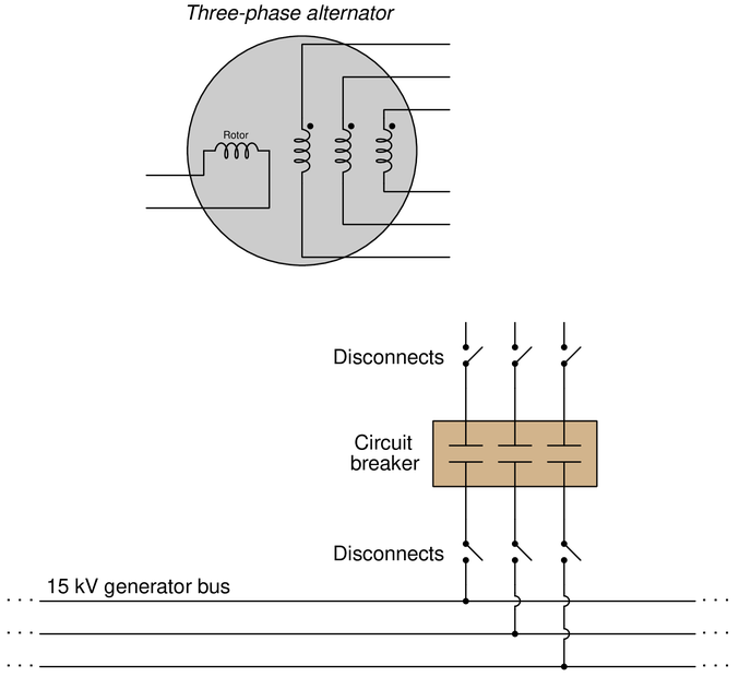
Each phase winding on the alternator is rated at 15 kV. The rotor winding is rated at 220 VDC. Sketch all necessary connections to make this alternator work as intended.
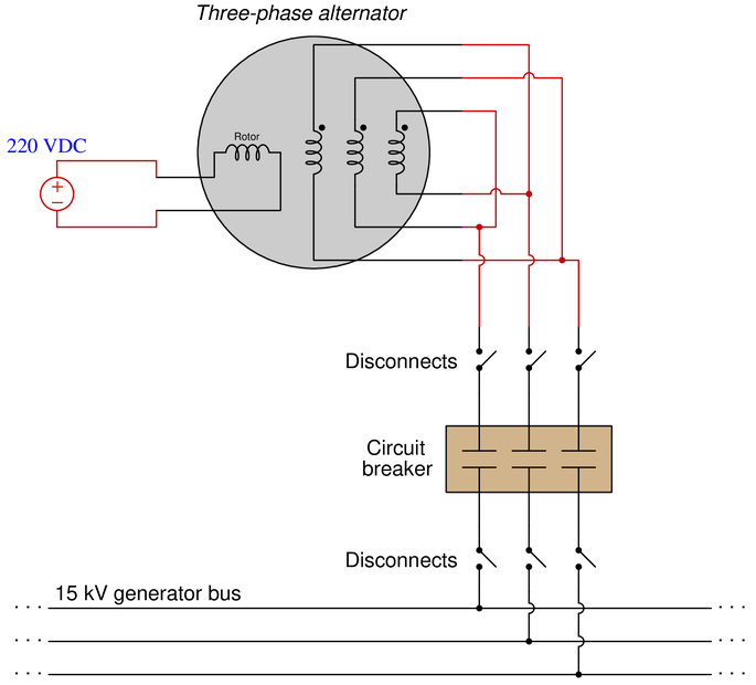
Reveal answerThis is one possible solution, but not the only one:
-
Question 8
An unbalanced wye-connected load receives power from a balanced 120/208 VAC source:

Calculate the current through each of the three lines (L1, L2, and L3), as well as the current through the neutral conductor:
{\bullet} $I_{L1}$ =
{\bullet} $I_{L2}$ =
{\bullet} $I_{L3}$ =
{\bullet} $I_{N}$ =
Reveal answerIn a 4-wire system such as this, each phase of the load is guaranteed to see the proper (balanced) phase voltage of 120 VAC. Thus, calculating each line current is the same as calculating each phase (resistor) current as follows:
$$I_{L1} = {120 \over 1500} = 0.08~A$$
$$I_{L2} = {120 \over 2300} = 0.0522~A$$
$$I_{L3} = {120 \over 800} = 0.15~A$$
Neutral conductor current will be the phasor sum of these three phase currents:
$$I_N = I_{L1} + I_{L2} + I_{L3}$$
Of course, we must remember that each of these three currents is phase-shifted from one another by 120 degrees. Arbitrarily choosing $I_{L1}$ as our zero-degree phase reference, and assuming an L1-L3-L2 rotation:
$$I_N = 0.08~A~\angle 0^o + 0.0522~A ~\angle 120^o + 0.15~A~\angle 240^o$$
$$I_N = 0.0873~A ~\angle 256^o$$
-
Question 9
A three-phase step-down transformer supplies 480 VAC to a pair of resistive loads. The secondary winding is “corner-grounded” on the X2 leg:
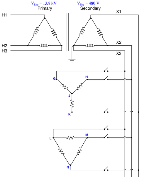
Determine the following phase-to-ground voltages in this system while both loads are energized:
{\bullet} $V_{G}$ =
{\bullet} $V_{H}$ =
{\bullet} $V_{J}$ =
{\bullet} $V_{K}$ =
{\bullet} $V_{L}$ =
{\bullet} $V_{M}$ =
{\bullet} $V_{N}$ =
Supposing the upper load has a total power dissipation of 8.4 kW and the lower load has a total power dissipation of 3.9 kW, calculate the amount of current through line H2.
Reveal answer{\bullet} $V_{G}$ = 0 volts
{\bullet} $V_{H}$ = 480 volts
{\bullet} $V_{J}$ = volts
{\bullet} $V_{K}$ = 480 volts
{\bullet} $V_{L}$ = 0 volts
{\bullet} $V_{M}$ = 480 volts
{\bullet} $V_{N}$ = 480 volts
The phase-to-ground voltage at point J must be calculated trigonometrically:
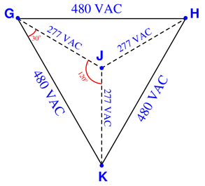
Each interior angle of the triangle GHK is 60$^{\circ}$. Angle JGK is 30$^{\circ}$. Angle GJK is 120$^{\circ}$. Phasor JK’s length may be calculated using the Law of Sines, where the ratio of side length to the sine of the opposite angle is constant for any triangle:
$${A \over \sin a} = {B \over \sin b}$$
$${480 \over \sin 120} = {V_{JK} \over \sin 30}$$
$$V_{JK} = \sin 30 \left({480 \over \sin 120}\right)$$
$$V_{JK} = 0.5 \left({480 \over 0.866}\right)$$
$$V_{JK} = 277.13~V$$
Total power in this system is 12.3 kW. The line current at the primary side of the transformer (assuming no power losses in the transformer) may be calculated as follows:
$$P_{total} = \sqrt{3} (I_{line}) (V_{line})$$
$$I_{line} = {P_{total} \over \sqrt{3} (V_{line})}$$
$$I_{line} = {12300 \over \sqrt{3} (13800)}$$
$$I_{line} = 0.5146~A$$
The grounding of the secondary is irrelevant to calculations of current and power, because that ground connection conducts no current at all and dissipates no power.
-
Question 10
Three-phase AC induction motors respond differently to the loss of one phase, depending on whether they are internally wye- or delta-connected:
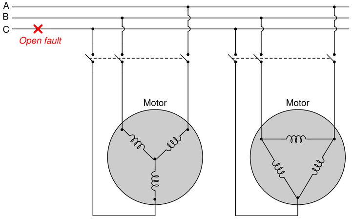
Which of these two motor designs will fare better in the event of a phase loss such as the open fault in phase C shown above, and why?
Reveal answerThe delta-connected motor will fare better, because it will still generate a polyphase (truly rotating) magnetic field, whereas the wye-connected motor will only generate an oscillating magnetic field. Also, the voltage across each phase winding of the delta-connected motor will remain the same as the line voltage, while the voltage across each phase winding of the wye-connected motor will decrease from what it was previous to the fault.
If the motors’ mechanical loads are sufficiently light, both motors will continue to rotate. However, the delta-connected motor will have a greater torque capacity in this phase-loss condition than the wye-connected motor due to the fact that its rotating magnetic field still maintains a definite direction of rotation and also that each of its phase windings receives the same (full) voltage as previously.If these consequences are not clear for you to see, you might wish to apply the problem-solving technique of adding quantitative values to the problem. Assign a line voltage (e.g. 480 VAC) to the incoming three-phase power conductors A, B, and C. Then, analyze the voltages at each phase winding of each motor before the fault versus after the fault. You may also calculate the phase angle for each of these winding voltages to see that the delta-connected motor still has three 120$^{\circ}$-shifted voltages powering it, while the wye-connected motor only has one voltage (single phase) powering it.
