 Facebook
 Google
 GitHub
 Linkedin
Electricity and Electronics
Transformer Circuit Calculations
-
Question 1
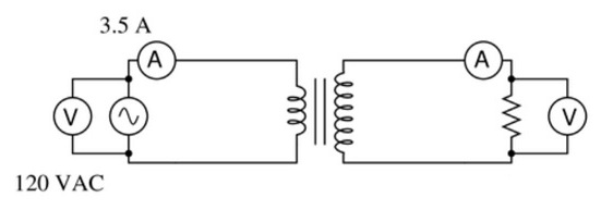
If an ‘isolation transformer’ (a transformer with the same number of turns in the primary and secondary coils) is connected between an AC source and an AC load, we will measure the same voltage and the same current at both source and load terminals:

If we calculate power output by the source and power dissipated by the load, the value is the same: 420 Watts ($P = I \cdot V$).
Now suppose we analyze a circuit containing a ‘step-up transformer’ (one with more turns of wire in the secondary coil than in the primary coil). With a step-up transformer, the load voltage will be greater than the supply voltage. In this example, I show a step-up transformer with a 1:2 step ratio:
Assuming the load resistance is completely different from the first (isolation transformer) circuit, what can you deduce about the load current and the power (both source and load) in this circuit? Is the load current less than the source current? Is the load current greater than the source current? Is the load power greater than the source power? Explain your answers.
Reveal answerThe basic physical law known as The Law of Conservation of Energy tells us that power cannot come from nowhere, or disappear into nowhere. If the power source is sending 420 watts into the transformer, then the load must be receiving 420 watts (neglecting any inefficiencies internal to the transformer). The transformer’s step ratio is completely irrelevant as far as power is concerned!
Notes:The only reason we might hesitate to that you can calculate load current precisely is because it doesn’t factor any losses fro mthe transformer. No real transformer is 100
The Conservation of Energy approach not only makes sense to students as they learn to calculate transformer behavior, but it is an excellent reinforcement of a basic physical law, a good understanding of which will serve them well throughout their careers.
-
Question 2
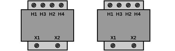
Industrial control power transformers are used to step down 480 or 240 volts to a level more acceptable for relay control circuitry: usually 120 volts. Some control power transformers are built with multiple primary windings, to facilitate connection to either a 480 volt or 240 volt AC power source:

Such transformers are usually advertised as having “240 $\times$ 480” primary windings, the “$\times$” symbol representing two independent windings with four connection points (H1 through H4).
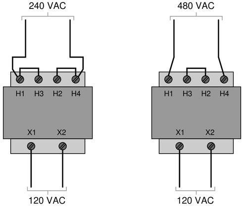
Show the connections on the four “H” terminals necessary for 240 volt operation, and also for 480 volt operation, on the following illustrations:
 Reveal answer
If the coils are to be considered a resistors, since the same series/parallel equations apply to both, then we could consider how high and low voltage might affect resistors.
With a 240 volt supply, this (relatively) low voltage can be dropped across both inductors, and placing them in parallel provides more energy and less loss, while inducing a voltage on the secondary coil.
In the case of (relatively) high 480 volts, the coils placed in series will allow both coils to drop 240 volts, exactly the same as before. Therefore, in both cases, two coils are dropping 240 volts, and the resulting voltage on the secondary coil will be the same.
 Notes:
This type of transformer is very common in industrial control systems. Discuss with your students why the primary winding terminals are arranged as they are (H1-H3-H2-H4), to facilitate near-terminal jumpering with metal clips.
-
Question 3
Calculate all listed values for this transformer circuit:

{\bullet} $V_{primary} = $
{\bullet} $V_{secondary} = $
{\bullet} $I_{primary} = $
{\bullet} $I_{secondary} = $Explain whether this is a step-up, step-down, or isolation transformer, and also explain what distinguishes the “primary” winding from the “secondary” winding in any transformer.
Reveal answerTo begin, we immediately know the voltage applied to the primary coil from the basic information provided.
{\bullet} $V_{primary} = 48~volts$
To identify the secondary voltage, the turns ratio of the transformer is 13000:4000, so the secondary will be lower voltage by a 13:4 ratio.
$${V_{primary} \over V_{secondary}} = {13 \over 4}$$
{\bullet} $V_{secondary} = 14.77~volts$The secondary current is the next simple calculation, based on Ohm’s Law:
$$I_{secondary}={V_{secondary} \over R_{secondary}}$$
{\bullet} $I_{secondary} = 98.5~mA$Finally, the current in the primary is found be either letting the power (V x I) of the secondary equal the power of the primary, or use the same turns ratio equations for voltage, but reverse the ratio, as current and turns re inversely proportional.
{\bullet} $I_{primary} = 30.3~mA$This is a step-down transformer.
The primary winding is connected to the source. There is no limitation on which side should have more or less windings, so it is unwise to assume that the higher turns indicate the primary side.
Notes:Most transformer problems are nothing more than ratios, but some students find ratios difficult to handle. Questions such as this are great for having students come up to the board in the front of the classroom and demonstrating how they obtained the results.
-
Question 4
Calculate the load voltage and load current in this transformer circuit:

$V_{load} =$
$I_{load} =$
Reveal answerThe first order of business is to determine the secondary (load) voltage by dividing the source voltage by the turns ratio.
$$Turns~Ratio={2390 \over 710}=3.366$$
$$V_{load}={V_{source} \over 3.366$$
$V_{load} = 8.318~V$
The load current is a simple application of Ohm’s Law:
$$I_{load}={V_{load} \over R_{load}}$$
$I_{load} = 23.77~mA$
Notes:Most transformer problems are nothing more than ratios, but some students find ratios difficult to handle. Questions such as this are great for having students come up to the board in the front of the classroom and demonstrating how they obtained the results.
-
Question 5
Calculate the load current and source current in this transformer circuit:

$I_{load} =$
$I_{source} =$
Reveal answerFirst, find the load current using the exact same method as the previous problem.
One important detail to note is the turns ratio, which is:
$$Turns~Ratio={1400 \over 3610}=0.388$$
This means when you divide the source voltage by the turns ratio, the load voltage will be higher. This is a step-up transformer.
$I_{load} = 72.73~mA$
Since this is a step up transformer, and the change in voltage and current are inversely related, a higher load voltage means we will actually have a smaller load current.
Calculate the power consumed by the load, and that will equal the power produced by the source.
$$P= V_{load} \cdot I_{load}=V_{source} \cdot I_{source}$$
And then solve for $I_{source}$
$I_{source} = 187.5~mA$
Notes:Most transformer problems are nothing more than ratios, but some students find ratios difficult to handle. Questions such as this are great for having students come up to the board in the front of the classroom and demonstrating how they obtained the results.
-
Question 6
Calculate all voltages and all currents in this circuit, given the component values and the number of turns in each of the transformer’s windings:
 Reveal answer
One obvious known property is the source voltage.
$V_{source} = 50~V$
This is a step-up transformer, with a turns ratio of 300:4500 (notice the primary is on the right side, along with the source).
Divide source voltage by turns ratio to determine the resistor’s voltage
$V_R = 750~V$
Ohm’s Law to determine the resistor’s current:
$I_R = 340.9~mA$
Source current can be found by assuming the $P_{source}$ equals the $P_{load}$, but there is another trick. The turns ratio was useful in determining the load voltage, but going back the other direction, it can be used the same way to determine the source current.
$$V_{load}={V_{source} \over Turns~Ratio}$$
$$I_{source}={I_{load} \over Turns~Ratio}$$
Note how we sitch the place of source and load as we toggle between voltage and current. This is because in the power equation, I and V will vary by equal, but opposite magnitudes to preserve power.
$I_{source} = 5.114~A$
Notes:This question checks students’ ability to relate the winding ratio to voltage and current ratios in a transformer circuit. The symbolism here is common in Europe, but not so common in the United States.
-
Question 7
Calculate all voltages and all currents in this transformer circuit, assuming the 170 ohm resistor carries a current of 5.8 mA:

{\bullet} $I_{secondary}$ =
{\bullet} $V_{secondary}$ =
{\bullet} $V_{primary}$ =
{\bullet} $I_{primary}$ =Reveal answerFirst, we know the current in the secondary coil because it is a series circuit and the current of one resistor is given.
{\bullet} $I_{secondary} = 5.8~mA$
The secondary voltage is found by adding all of the resistor voltages in series; these can be found by using Ohm’s Law $V=I \cdot R$.
{\bullet} $V_{secondary} = 3.045~V$
Since this is a step-down transformer (more turns on the primary), we can find the primary voltage by multiplying the secondary voltage by the turns ratio: 3800:550.
{\bullet} $V_{primary} = 21.04~V$
In a likewise fashion, the primary current is found by dividing the secondary current by the turns ration 3800:550.
{\bullet} $I_{primary} = 839.5~\mu A$
Notes:Most transformer problems are nothing more than ratios, but some students find ratios difficult to handle. Questions such as this are great for having students come up to the board in the front of the classroom and demonstrating how they obtained the results.
-
Question 8
Calculate all voltages and all currents in this transformer circuit, assuming the 5 ohm resistor carries a current of 10 amps:

{\bullet} $V_{secondary}$ =
{\bullet} $I_{secondary}$ =
{\bullet} $V_{primary}$ =
{\bullet} $I_{primary}$ =Reveal answerThe secondary voltage is the first objective. Since we know the current and resistance of one parallel load, this will directly determine the voltage of the secondary coil: $V=I \cdot R$.
{\bullet} $V_{secondary} = 50~V$
Knowing the voltage of both load resistors, we can calculate the current through the 4 ohm resistor as well.
The total secondary current is the sum of both resistor currents.
{\bullet} $I_{secondary} = 22.5~A$
As before, the secondary voltage multiplied by the turns ratio will yield the primary voltage.
As a logic check, which coil should have higher voltage? The one with more coils: the primary coil in this case.
1450:900 is the ratio.
{\bullet} $V_{primary} = 80.56~V$
The primary current can be found by equating the primary and secondary power and solving for current.
Alternatively, the secondary current can be divided by the turns ratio to yield the primary current.
As a logic check, which side should have higher current? The one with fewer coils: the secondary side in this case.
{\bullet} $I_{primary} = 13.97~A$
Notes:Most transformer problems are nothing more than ratios, but some students find ratios difficult to handle. Questions such as this are great for having students come up to the board in the front of the classroom and demonstrating how they obtained the results.
-
Question 9
Calculate all voltages and all currents in this transformer circuit, assuming the 3.3 kΩ resistor drops 40 volts:

{\bullet} $V_{source}$ =
{\bullet} $V_{primary}$ =
{\bullet} $V_{secondary}$ =
{\bullet} $I_{source}$ =
{\bullet} $I_{primary}$ =
{\bullet} $I_{secondary}$ =Reveal answerIn this example, we will solve the voltages and currents in the most reasonable order, based on what we know.
First, we can calculate the secondary current by applying Ohm’s Law to 3.3 kΩ resistor with 40 volts.
{\bullet} $I_{secondary} = 12.12~mA$
Use this same current to solve for the voltage of the other resistor, and the sum of those voltages is the secondary voltage.
{\bullet} $V_{secondary} = 46.06~V$
Secondary voltage multiplied by the turns ratio (900:2200) is the primary voltage. Remember, which one should have more voltage? The one with more turns: the secondary, in this case.
{\bullet} $V_{primary} = 18.84~V$
Since the primary side of the circuit is a parallel circuit, the primary voltage is also the voltage across the 400 Ω resistor, and it is also the source voltage.
{\bullet} $V_{source} = 18.84~V$
The primary current is determined by dividing the secondary current by the turns ratio (explanation in previous problems).
Again as a logical guide, the side with fewer turns should have more current.
{\bullet} $I_{primary} = 29.63~mA$
Finally, the source current is the sum of the primary current + the current through the 400 Ω resistor, the latter of which is found through use of Ohm’s Law, since we know the resistor’s voltage.
{\bullet} $I_{source} = 76.74~mA$
Notes:Most transformer problems are nothing more than ratios, but some students find ratios difficult to handle. Questions such as this are great for having students come up to the board in the front of the classroom and demonstrating how they obtained the results.
-
Question 10
Calculate all voltages and all currents in this transformer circuit, assuming the 3.3 kΩ resistor drops 13 volts:

{\bullet} $V_{source}$ =
{\bullet} $V_{primary}$ =
{\bullet} $V_{secondary}$ =
{\bullet} $I_{source}$ =
{\bullet} $I_{primary}$ =
{\bullet} $I_{secondary}$ =Reveal answerIn this example, we will solve the voltages and currents in the most reasonable order, based on what we know.
First, we can calculate the secondary current by applying Ohm’s Law to 3.3 kΩ resistor with 13 volts.
{\bullet} $I_{secondary} = 3.939~mA$
Use this same current to solve for the voltage of the other resistor, and the sum of those voltages is the secondary voltage.
{\bullet} $V_{secondary} = 14.97~V$
Secondary voltage multiplied by the turns ratio (700:2200) is the primary voltage. Remember, which one should have more voltage? The one with more turns: the secondary, in this case.
{\bullet} $V_{primary} = 4.763~V$
The primary current is determined by dividing the secondary current by the turns ratio (explanation in previous problems).
Again as a logical guide, the side with fewer turns should have more current.
{\bullet} $I_{primary} = 12.38~mA$
Since the primary side features a series circuit, the 45 Ω resistor as well as the source, both share the primary current.
{\bullet} $I_{source} = 12.38~mA$
Finally, the source voltage is the sum of the primary voltage + the voltage of the 45 Ω resistor, which is found by applying Ohm’s Law to the resistor: $V= I \cdot R$.
{\bullet} $V_{source} = 5.32~V$
-
Question 11
Suppose a power system were delivering AC power to a resistive load drawing 150 amps:

Calculate the load voltage, load power dissipation, the power dissipated by the wire resistance ($R_{wire}$), and the overall power efficiency ($\eta = {P_{load} \over P_{source}}$).
$E_{load} = $
$P_{load} = $
$P_{lines} = $
$\eta = $Now, suppose we were to use a pair of perfectly efficient 10:1 transformers to step the voltage up for transmission, and back down again for use at the load. Re-calculate the load voltage, load power, wasted power, and overall efficiency of this system:
$E_{load} = $
$P_{load} = $
$P_{lines} = $
$\eta = $Reveal answerSimple system (no transformers):
The losses in the wire result from 150 amps passing through 2x 0.1 Ω resistors. Although not much, this causes a loss of 30 V total, leaving only 210 V for the load.
Multiplying this 210 V by the 150 A current for power, and comparing this to the 240 V source supplying 150 A, the resulting efficiency is quite poor.
$E_{load} = 210~V$
$P_{load} = 31.5~kW$
$P_{lines} = 4.5~kW$
$\eta = 87.5$Complex system (with transformers):
In this case, the transformers provide a high-voltage and low-current situation in the wires. Now with only 15 A in the wire, the total voltage loss from the wire is only 3 V total. Now, stepping this voltage loss back down the load, the loss of voltage at the load is only 0.3 V, leaving 239.7 V for the load.
Comparing the voltage at the load and source (since current is identical) the efficiency is FAR better.
$E_{load} = 239.7~V$
$P_{load} = 35.96~kW$
$P_{lines} = 45~W$
$\eta = 99.88$Notes:An example like this usually clarifies the benefits of using AC instead of DC for transmission of large amounts of electrical power over substantial distances, better than simply telling students why transformers are used in power systems. Even with modest power losses in the transformers (say, 3
In discussing the follow-up question, be sure to bring up safety as a consideration if none of your students do.
-
Question 12
How much current will be output by a current transformer if the load current is 350 amps and the CT ratio is 600:5?
 Reveal answer
The CT ratio is a measure of the current at the primary to the current at the secondary. Given the ratio of 600:5, which reduces to 120:1, the current in the primary is 120x higher than the current in the secondary.
$${I_{primary} \over I_{secondary}}={600 \over 5}$$
Secondary current = 2.917 amps
Notes:This question is an exercise in mathematical ratios.

It will be very useful if you show the formulas or how you got the answers. Thank you